The BeagleBone is a very popular single board computer, best applied to real-time applications where you need to blink LEDs really, really fast. Over the years, the BeagleBone has been used for stand-alone CNC controllers, the brains behind very large LED installations, and on rare occasions has been used to drive CRTs. If you just want a small Linux board, get a Pi. If you want to do something interesting with hardware, get a BeagleBone.
The BeagleBone ecosystem has grown a lot in the last year, from the wireless and Grove connector equipped BeagleBone Green, the robotics-focused BeagleBone Blue, the Zoolander-inspired Blue Steel. Now there’s a new BeagleBone, built around a very interesting System on Module introduced earlier this year.
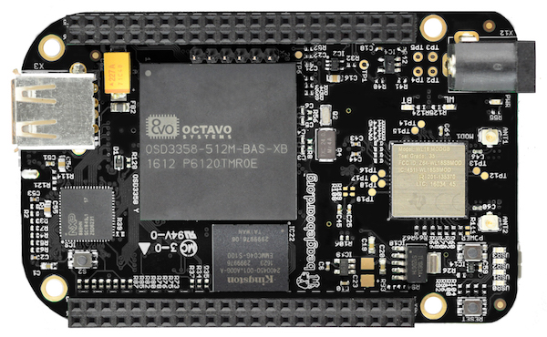
The new board is called the BeagleBone Black Wireless, and it brings to the table all you know and love about the BeagleBone. There’s a 1GHz ARM355x with two 32-bit 200MHz PRUs for the real-time pin toggling. RAM is set at 512MB, with 4GB of eMMC Flash and Debian pre-installed, and a microSD card for larger storage options. The new feature is wireless connectivity: a TI WiFi and Bluetooth module with provisions for 802.11s replaces the old Ethernet connector.
Taken at face value, the new BeagleBone Black Wireless deserves a mention — it’s a BeagleBone with wireless — but isn’t particularly noteworthy. But when you get to the gigantic brick of resin dropped squarely in the middle of the board does the latest device in the BeagleBone family become very, very interesting. The System on Module for this version of the BeagleBone is the BeagleBone On A Chip released a few months ago. The Octavo Systems OSD335x is, quite literally, a BeagleBone on a chip. It’s a BGA with big balls, making it solderable with hand-applied solder paste and a toaster oven reflow conversion. In fact, the BeagleBone Wireless was designed by [Jason Kridner] in Eagle as a 6-layer board. It’s still a bit beyond the standard capabilities of OSHPark, but the design can still be cut down, and shows how this BeagleBone on a Chip can be applied to other Open Hardware projects.
In the early 1930s, Reginald Denny, an English actor living in Los Angeles, stumbled upon a young boy flying a rubber band-powered airplane. After attempting to help the boy by adjusting the rubber and control surfaces, the plane spun into the ground. Denny promised he would build another plane for the boy, and wrote to a New York model manufacturer for a kit. This first model airplane kit grew into his own hobby shop on Hollywood Boulevard, frequented by Jimmy Stewart and Henry Fonda.
The business blossomed into Radioplane Co. Inc., where Denny designed and built the first remote controlled military aircraft used by the United States. In 1944, Captain Ronald Reagan of the Army Air Forces’ Motion Picture unit wanted some film of these new flying targets and sent photographer David Conover to the Radioplane factory at the Van Nuys airport. There, Conover met Norma Jeane Dougherty and convinced her to go into modeling. She would later be known as Marilyn Monroe. The nexus of all American culture from 1930 to 1960 was a hobby shop that smelled of balsa sawdust and airplane glue. That hobby shop is now a 7-Eleven just off the 101 freeway.
Science historian James Burke had a TV wonderful show in the early 90s – Connections – where the previous paragraphs would be par for the course. Unfortunately, the timbre of public discourse has changed in the last twenty years and the worldwide revolution in communications allowing people to instantaneously exchange ideas has only led to people instantaneously exchanging opinions. The story of how the Dutch East India Company led to the rubber band led to Jimmy Stewart led to remote control led to Ronald Reagan led to Death of a Salesman has a modern fault: I’d have to use the word ‘drone’.
The word ‘propaganda’ only gained its negative connotation the late 1930s – it’s now ‘public relations’. The phrase ‘global warming’ doesn’t work with idiots in winter, so now it’s called ‘climate change’. Likewise, quadcopter pilots don’t want anyone to think their flying machine can rain hellfire missiles down on a neighborhood, so ‘drone’ is verboten. The preferred term is quadcopters, tricopters, multicopters, flying wings, fixed-wing remote-controlled vehicles, unmanned aerial systems, or toys.
I’m slightly annoyed by this and by the reminder I kindly get in my inbox every time I use the dreaded d-word. The etymology of the word ‘drone’ has nothing to do with spying, firing missiles into hospitals, or illegally killing American civilians. People like to argue, though, and I need something to point to when someone complains about my misuse of the word ‘drone’. Instead of an article on Hollywood starlets, the first remote control systems, and model aviation, you get an article on the etymology of a word. You have no one else to blame but yourself, Internet.
So you like watching stupid stuff? Here you go, a scene from Bones that tops the infamous ‘IP backtrace with Visual Basic’ or ‘four-handed keyboard’ scenes from other TV shows. Someone hacked the bones by embedding malware in a calcium fractal pattern. Also, when she uses the fire extinguisher, she doesn’t spray the base of the fire.
Raspberry Pi! You have no idea how good the term Raspberry Pi is for SEO. Even better is Raspberry Pi clusters, preferably made with Raspberry Pi Zeros. Here’s a Raspberry Pi hat for four Raspberry Pi Zeros, turning five Raspberry Pis into a complete cluster computer. To be honest and fair, if you’re looking to experiment with clusters, this probably isn’t a bad idea. The ‘cluster backplane’ is just a $2 USB hub chip, and a few MOSFETs for turning the individual Pis on and off. The Zeros are five bucks a pop, making the entire cluster cost less than two of the big-boy sized Pi 3s.
Do you think you might have too much faith in humanity? Don’t worry, this video has you covered.
Hacking on some Lattice chips? Here’s a trip to CES for you. Lattice is holding a ‘hackathon’ for anyone who is building something with their chips. The top prize is $5k, and a trip to next year’s CES in Vegas, while the top three projects just get the trip to Vegas. If you already have a project on your bench with a Lattice chip, it sounds like a great way to wait an hour for a cab at McCarran.
UPSat. What’s an upsat? Not much, how about you? The first completely open source hardware and software satellite will soon be delivered to the ISS. Built by engineers from the University of Patras and the Libre Space Foundation, the UPSat was recently delivered to Orbital ATK where it will be delivered to the ISS by a Cygnus spacecraft. From there, it will be thrown out the airlock via the NanoRacks deployment pod.
The Voyager Golden Record is a message in a bottle thrown into the cosmic ocean and a time capsule from Earth that may never be opened. Now it’s a Kickstarter. Yes, this record is effectively Now That’s What I Call Humanity volume 1, but there are some interesting technical considerations to the Voyager Golden Record. To the best of my knowledge, no one has ever tried to extract the audio and pictures from this phonographic time capsule. The pictures included in the Golden Record are especially weird, with the ‘how to decode this’ message showing something like NTSC, without a color burst, displayed on a monitor that is effectively rotated 90 degrees counterclockwise from a normal CRT TV. Want to know how to get on Hackaday? Get this Golden Record and show an image on an oscilloscope. I’d love to see it, if only because it hasn’t been done before by someone independent from the original project.
In the last (and first) post in this series, we took a look at Eagle. Specifically, we learned how to create a custom part in Eagle. Our goal isn’t just to make our own parts in Eagle, we want to make schematics, boards, and eventually solder a few PCBs.
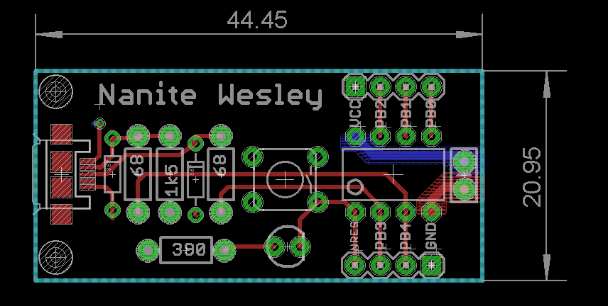
The board we’ll be making, like all of the boards made in this Creating A PCB In Everything series, is the Nanite Wesley, a small USB development platform based on the ATtiny85. This board has less than a dozen parts, most of which are through-hole. This is the simplest PCB I can imagine that has sufficient complexity to demonstrate how to make a board.
With that said, let’s get onto the second part of our Eagle tutorial and lay out our circuit board.
On the eve of the New York Maker Faire, Hackaday is throwing a meetup in the heart of Manhattan. Join us next Thursday for a low-key get-together, a few talks on assistive technologies, and a demo of the coolest new tool in recent memory.
Although these meetups are highly informal (and bringing some of the cool stuff you’ve built is encouraged), we do have a few speakers lined up. Holly Cohen and John Schimmel of DIYAbility are speaking about using homebrew devices for making everyone’s life easier. Johnny Falla of the Enable Community Foundation will give a talk about using 3D printing technology to make hyper-affordable prosthetic devices for underserved populations. Chad Leaman will be representing the Neil Squire Society and will speak about using technology to empower people with disabilities.
As always, snacks and drinks will be provided, and like all Hackaday meetups, bring some cool gear or whatever project you’re working on along with you. This bring-a-hack isn’t a competition, but if it was, we know who would win. Nisan Larea will be attending the meetup, demoing the Wazer desktop waterjet cutter. We caught a glimpse of this machine in San Francisco, and it’s amazing. If you want to see the Wazer waterjet before Maker Faire, this is your chance.
This month’s Hackaday NYC meetup will be at Pivotal Labs, 625 Avenue of the Americas, on Thursday, September 29. It would be really, really cool if you could RSVP beforehand.
This is Hackaday’s pre-game for the World Maker Faire. We’ll be attending, scoping out all the coolest projects and products from this year’s NYC Maker Faire. Find one of the Hackaday crew at the faire, and we’ll hook you up with some swag.
For the first in a series of posts describing how to make a PCB, we’re going with Eagle. Eagle CAD has been around since the days of DOS, and has received numerous updates over the years. Until KiCad started getting good a few years ago, Eagle CAD was the de facto standard PCB design software for hobbyist projects. Sparkfun uses it, Adafruit uses it, and Dangerous Prototypes uses it. The reason for Eagle’s dominance in a market where people don’t want to pay for software is the free, non-commercial and educational licenses. These free licenses give you the ability to build a board big enough and complex enough for 90% of hobbyist projects.
Of course, it should be mentioned that Eagle was recently acquired by Autodesk. The free licenses will remain, and right now, it seems obvious Eagle will become Autodesk’s pro-level circuit and board design software.
Personally, I learned PCB design on Eagle. After a few years, I quickly learned how limited even the professional version of Eagle was. At that point, the only option was to learn KiCad. Now that Eagle is in the hands of Autodesk, and I am very confident Eagle is about to get really, really good, I no longer have the desire to learn KiCad.
With the introduction out of the way, let’s get down to making a PCB in Eagle.
A few years ago, I wrote a few columns titled Making A Thing. These columns were a tutorial of sorts for several different 3D modeling programs. This column wasn’t meant to be a complete guide to modeling an object in OpenSCAD or SolidWorks, it was just step-by-step instructions on how to make one specific thing with one specific piece of software.
More than a few people in the Hackaday community found this column useful or at the very least an interesting pedagogical device. When starting out with any kind of productivity software, you don’t need to know how to do everything, you just need to know how to do the most common tasks.
Since the Making A Thing column was so popular, I felt it was time to revive this idea with another design task we often face. As you have already guessed, we’re going to be making printed circuit boards. Continuing the unique tutorial format created in the previous iteration of this column, Making a PCB will build one specific circuit in multiple EDA suites.
The Circuit
The entire concept of demonstrating how to build one thing in a specific software package necessitates a model thing. Before I even begin writing the first Making A PCB column, I need to design something that’s sufficiently complex but still relatively simple, and something that’s hopefully somewhat useful. Breakout boards are extremely simple, perhaps too much. In the course of these programs, I’ll need to demonstrate how to make a part in each specific software suite, so fewer pins are better.
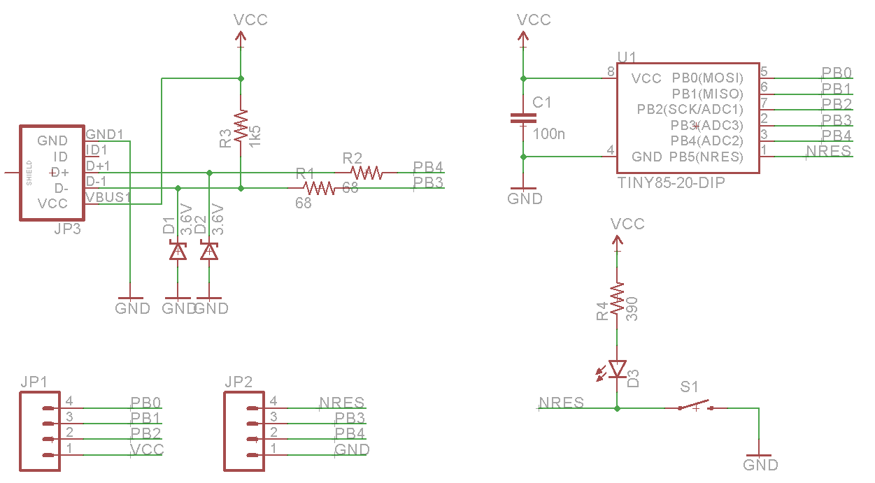
Lacking any creativity of my own, I’ve settled on a very small ATtiny85 Arduino derivative from Tim a.k.a. [cpldcpu]. Tim’s Nanite 85 is an exceptionally small Arduino-compatible board based on the ATtiny85, complete with a USB port, LED, and a few pins of I/O. It’s simple but sufficiently complex to give an introduction to a PCB design suite.
I’m not going to outright copy Tim’s Nanite 85, though. It’s much clearer if parts aren’t stacked on top of each other, and I’d like to give myself a little breathing room on the layout. I’ve redesigned the circuit of the Nanite 85 to use mostly through-hole parts on a slightly larger board. I’m calling my version the Nanite Wesley, and if you get that reference, thumbs up for you.
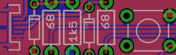
The schematic for the Nanite WesleyThe Nanite Wesley board. Copper pours not shown
Is this how a board should be laid out? No, absolutely not. I could probably do this as a single-layer board. This is a very inefficient layout, and I like rounded corners on my boards. It’s good enough, though, and it works. This is meant to be a tutorial on how to use a PCB design package, not a tutorial on how to design a PCB. Your criticisms in this regard are noted and ignored.
What These Tutorials Will Consist Of
You cannot use a PCB design package until you know how to make a part. Yes, Eagle has wonderful libraries for almost everything you can imagine, KiCad has plenty of parts on the Internet, and if you’re using a cloud-based PCB software, almost everything will be provided for you. If you make a PCB, eventually you’ll have to make your own part, though, and each tutorial will begin with making a DIP-8 ATtiny85. Everything else on this board is a jellybean part. Either way, the process of making a part and package for a Zener is the same as making one for a microcontroller.
The next part of the tutorial will consist of schematic capture. This means placing the parts in the schematic, drawing wires between the pins and pads, and naming them. From there, it’s time to actually make a board, and this means dropping the parts down, putting traces between all the pins, doing the board outline, pouring copper, and mechanical considerations.
With the schematic and board designed, it will be time to send it off to a fab house. For Eagle and KiCad, this is easy; OSHpark accepts Eagle .brd and KiCad .pcb files, but this is cheating. We’re going to use CAM to generate real Gerber files. If you make enough PCBs, you’ll have to learn it eventually.
Caveats and Poor Design
There are a lot of things that go into making a ‘proper’ PCB, including isolation, direct traces to decoupling capacitors, making sure pixies don’t go around sharp corners and a thousand other items that won’t be discussed in these tutorials. There’s a reason I won’t be discussing this. This is a guide on how to use a PCB design tool, not how to design a PCB.
What else should I do?
As you can probably guess from the schematic above, the first PCB software I’m going to cover is Eagle. KiCad is on the list, as is Fritzing, Altium CircuitMaker, and OrCAD. In the interests of putting PCB design in a historical context, I have a copy of AutoTRAX and an old DOS machine. I’ll also be covering a few of the cloud-only design tools such as Upverter.
That’s enough software suites to get started, but as with the Making A Thing series, I’m going to be looking for suggestions from the peanut gallery. I can’t change the circuit I’m making, as that’s the entire point of this series, but I am looking for suggestions on other tools to cover. What else can I do? Want me to grab a piece of copper clad board, sticker overlays, and some photostatic film? I can do that. Are you at a web-based EDA startup, and want some free advertising? Leave a note in the comments.
Thanks to our efforts to slowly improve the backend of Hackaday, you’ll be able to access all the Making A PCB In Everything posts from the series list below.