Animated GIFs On A Graphing Calculator

The TI-84 Plus graphing calculator has a Z80 processor, 128 kilobytes of RAM, and a 96×64 resolution grayscale LCD. You might think a machine so lean would be incapable of playing video. You would be right. Animated GIFs, on the other hand, it can handle and [searx] is here to tell you how.

Before assembling his movie, [searx] first needed to grab some video and convert it to something the TI-84 could display. For this, he shot a video and used Premiere Pro to reduce the resolution to 95 by 63 pixels. These frames were saved as BMPs, converted to monochrome, renamed to pic0 through pic9, and uploaded to the calculator’s RAM.

To display the animated GIF, [searx] wrote a small program to cycle through the images one at a time. This program, like the images themselves, were uploaded to the calculator over the USB connector. Playing these animated GIFs is as simple as calling the program, telling it how fast to display the images, and standing back and watching a short flip-book animation on a calculator.

Astronaut Or Astronot: Vote For The Hackaday Prize!

Just in case we haven’t hammered it into your skull quite yet, we’re having a little contest over on Hackaday.io. It’s The Hackaday Prize, where everyone on Hackaday.io is invited to build something cool for the chance of winning a trip to space and hundreds of other prizes.

We know not everyone has the desire, skills, or the time to build a project, but that doesn’t mean you can’t still contribute. We’re holding a community voting round right now. Each week, we have a new round of community voting with a new theme. This week, we’re asking the Hackaday.io community to select the project that is most likely to be widely used. What do you have to do to participate? Just go over to the voting page, and choose between two projects our especially fair voting algorithm pulled from current Hackaday Prize entries. Pick the project that best meets the theme of the week.

Why would anyone want to do this? This Friday, I’ll be taking a look at everyone on Hackaday.io, pulling a number out of a hat, and if that person voted in the current round of voting, they win a thousand dollar gift card to the Hackaday store. We’re also giving away Hackaday t-shirts to random people who have voted each week.

The only losing move is not to play, so go over to the voting page and pick the projects that best meet the theme, “most likely to be widely used.”

Microcassette Recorders Become A Tape Delay

Long before audio engineers had fancy digital delays, or even crappy analog delays, there were tape delays. Running a tape around in a loop with a record and play head is the basis of the Echoplex and Space Echo, and both of these machines are incredible pieces of engineering.

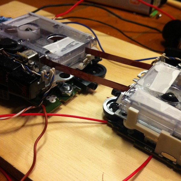
Microcassette recorders are not, in general, incredible pieces of engineering. They do, however, have a strip of magnetic tape, a record head, and a play head. Put two of them together, and you can build your own tape delay.

The basic principle of a tape delay is simple enough – just run a loop of tape round in a circle, through a record and playback head, record some audio, and send the output to an amplifier. In practice, it’s not that simple. [dogenigt] had to manufacture his own tape loop from microcassettes, a process that took far too long and was far too finicky.

For a control circuit, [dogenigt] is using four audio pots and one linear pot for speed control. The audio pots are responsible for input gain, feedback, the amplitude of the clean signal, and the output of the signal after it’s been run through the delay.

Apart from being one of those builds that’s very dependent on the mechanical skill of the builder, it’s a pretty simple delay unit, with all the electronics already designed for a stripboard layout. You can hear an example of what it sounds like below.

Continue reading “Microcassette Recorders Become A Tape Delay”

Hackaday Prize Entry: Tearing Down A Tesla

We’ve seen a few people tear down the drive trains from electric vehicles like the Nissan Leaf, Prisuses, or the Chevy Volt. We’ve also seen someone tear down the battery pack found in a Tesla Model S. What we haven’t seen until now is a reverse engineering of the Tesla Model S drive train.

A fortuitous circumstance landed [Michal] the crown jewel of the Tesla Model S – the 310kW, 590Nm drive train. Exactly how and where [Michal] landed this gigantic powerful motor is a question that remains unanswered, and the question unasked. We might not want to know.

Now that he has a motor, the name of the game is figuring out how to drive it. Usually that means capturing data from the CAN bus and replaying that data. This isn’t what [Michal] is doing; instead, he’s using a motor controller he developed for the Chevy Volt and Toyota Prius. It’s going to be a lot of work, but that’s only because these gigantic EV motors and controllers are pretty rare on the used market now. Give it a few years, and the work [Michal] is putting in now will pay off in hundreds of DIY electric vehicles.


The 2015 Hackaday Prize is sponsored by:

Ask Hackaday (And Adafruit): The New CEO Of MakerBot

Just a few years ago, MakerBot was the darling of the Open Hardware community. Somehow, in the middle of a garage in Brooklyn, a trio of engineers and entrepreneurs became a modern-day Prometheus, capturing a burgeoning technology into a compact, easy to use, and intoxicating product. A media darling was created, a disruptive technology was popularized, and an episode of the Colbert Report was taped.

The phrase ‘meteoric rise’ doesn’t make sense, and since then the reputation of MakerBot has fallen through the floor, crashed through the basement, and is now lodged in one of the higher circles of hell. It’s not surprising; MakerBot took creations from their 3D object hosting site, Thingiverse, and patented them. The once-Open Source line of 3D printers was locked up behind a closed license. The new MakerBot extruder – the Smart Extruder – is so failure prone MakerBot offers a three pack, just so you’ll always have a replacement on hand. False comparisons to Apple abound; Apple contributes to Open Source projects. The only other way for a company to lose the support of the community built around it so quickly would be a name change to Puppy Kickers, LLC.

In the last few months, figurehead CEO of MakerBot [Bre Pettis] was released from contractual obligations, and MakerBot’s parent company, Stratasys, has filled the executive ranks with more traditional business types. It appears PR and Marketing managers have noticed the bile slung at their doorstep, and now MakerBot is reaching out to the community. Their new CEO, [Jonathan Jaglom] specifically requested a hot seat be built at Adafruit for an open discussion and listening meeting. Yes, this means Makerbot is trying to get back on track, winning the hearts and minds of potential customers, and addressing issues Internet forums repeat ad nauseam.

If you’ve ever wanted to ask a CEO how they plan to stop screwing things up, this is your chance. Adafruit is looking for some direction for their interview/listening meeting, and they’re asking the community for the most pressing issues facing the 3D printing community, the Open Source community, and MakerBot the company.

Already on the docket are questions about MakerBot and Open Source, MakerBot’s desire to put DRM in filament, the horrors of the Smart Extruder and the 5th generation MakerBots, problems with Thingiverse, and the general shitty way MakerBot treats its resellers.

This isn’t all Adafruit wants to ask; the gloves are off, nothing is off the table, and they’re looking for questions from the community. What would you like to ask the MakerBot CEO?

Personally, the best interview questions are when the interviewee’s own words are turned around on them. By [Jonathan Jaglom]’s own admission, the barrier to entry for 3D design work has been substantially lowered in the last three years, ostensibly because of incredible advances in Open Source projects. Following this, do MakerBot and Stratasys owe a debt to Open Source projects, and should Stratasys contribute to the rising tide of Open Source development?

That’s just one question. There will, of course, be many more. Leave them down in the comments. “You are not [Tim Cook],” while a valid statement in many respects, is not a question.


A Game Pad For The Apple II

[Quinn Dunki] has been hard at work building a Teddy Top – an Apple IIc Plus modified for a road warrior. It has a 3.5 inch disk drive, runs at a blistering four megahertz, and has a beautiful integrated color LCD. It would be a shame to have such a great machine and no way to play games as they were intended, so [Quinn] set about building a game pad for her lovable Apple II.

The Apple II joystick port isn’t as simple as an Atari or Commodore joystick port. Where the bog-standard Atari joystick is basically just a bunch of switches connected to pins, the Apple II joystick is analog. Weird, and even weirder is the value of the pots in these joysticks: 150kΩ. Somehow or another, nobody makes pots in this value any more. Luckily the hardware in these joysticks is well documented, and shoehorning in modern components isn’t that bad.

The Apple joystick has a bit of circuitry – a 556 timer chip that reads the values of each pot and converts that into a stream of 0s and 1s for the Apple. The joystick [Quinn] found for her game pad is an analog thumb stick on a neat breakout board manufactured by Parallax. This analog joystick has 10kΩ pots in it, and that just won’t work with the 556 timer chip. However, since this is just resistors and a 556 chip, adjusting some of the values on the original schematics does the trick. [Quinn] added a few capacitors to her circuit, and everything worked beautifully.

With the electronics down, she turned her attention to the case for her Apple II road warrior enclosure. She recently picked up a 3D printer, which means she’s new to 3D printing. After spending a few hours designing a controller in 123D Design, she sent the files over to the printer. Warping happened. She tried an ABS slurry. The part was stuck to the bed. It took a few tries (purple glue sticks are awesome, [Quinn]), but she eventually got her plastic enclosure printed out, and the circuitry installed. The result is a portable computer, with a custom controller, playing Lode Runner. Can’t beat that.

Hackaday Prize Entry: An Open Source Graphics Card

For last year’s Hackaday Prize, [PK] tried to build a video card for microcontrollers and headless Linux systems. It was only 640×480 resolution VGA, but the entire project was designed around a CPLD communicating with a microcontroller over SPI. This prize entry was, by [PK]’s own admission, a failure. It was late, but now he’s had an entire year to perfect his design. That means he can enter version two of his VGATonic in The Hackaday Prize.

The VGATonic version 2 uses a Xilinx XC95144XL CPLD for the VGA timing, and an ATTiny 2313a to read the SPI bus. Video memory is four megabits of static RAM. That’ls pretty much all you need for the most basic VGA graphics card, and all of this is packed onto a 3×3 inch PCB.

You can do a lot with 640×480 8-bit graphics running at 25FPS. In the video below, [PK] has a ‘hello world’ of sorts, Doom, running on a Raspberry Pi 2 with his SPI graphics card. Yes, it’s a graphics card for the Raspberry Pi, and it looks really good.

Further refinements of the design will include some primitive graphics routines. Not OpenGL or anything fancy, just something to reduce the number of writes on the SPI bus. It’s a great project, and perfect if you want to add video out to an Intel Galileo or other microcontroller project. [PK] has a video demo, you can check that out below.


The 2015 Hackaday Prize is sponsored by:

Continue reading “Hackaday Prize Entry: An Open Source Graphics Card”