A 6502 Overlay Debugger

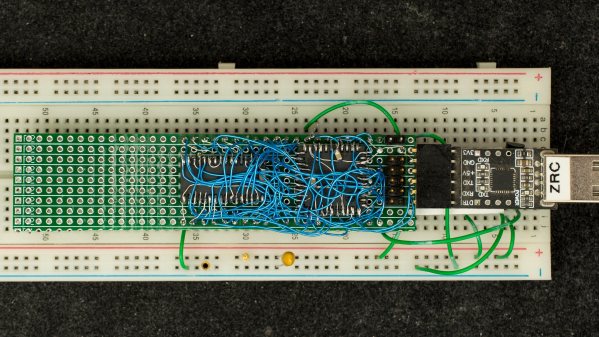
Retired hardware engineer [Plasmode] recently took on the challenge of building a debugger for the 6502 designed to sit atop the microprocessor while seated in a solder less breadboard. The result is the Diagnostic Overlay for W65C02 Breadboard, consisting of 128 kB SRAM and a 1250-gate CPLD. Except being 0.8 in wide, the overlay debugger is otherwise the same size as the 6502’s 40-pin DIP package, so it doesn’t overhang other portions of your circuit.
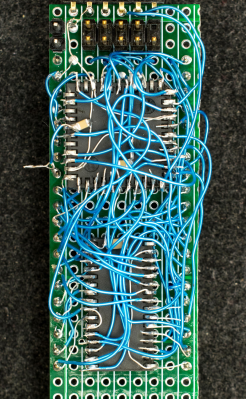
Being an initial concept prototype, [Plasmode] mounted the chips dead-bug style on perf board — a process he himself found tiring. If he builds additional debuggers, presumably he will consider making a PCB.

The prototype was constructed using point-to-point soldering with 30-ga wire wrap wire.  It was all done under the inspection microscope.  There are not many connections, but they are rather tedious so I can only do a dozen or so wires per session.  It took me 2 days and several hours total to finish the prototype board.

This design is based on the CRC65 Frugal 6502 Single Board Computer, of course omitting the 6502 itself. Instead of a physical ROM memory chip, he implemented a 64-byte boot loader inside the CPLD and a serial port. This lets him to bootstrap the system over the serial port. He plans on expanding this to include other DIP-packaged retro microprocessors in the future. Check out his Hackaday.io project page ( above ). If you want to dig deeper, he posted the schematics here.

Bringing An ADM-3A Back To Life

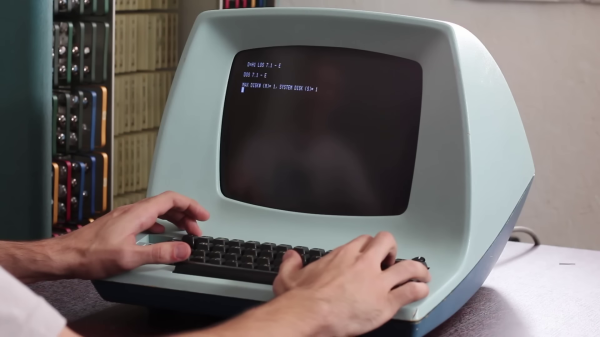
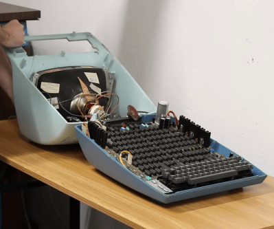
[David] at Usagi Electric ended up with an old Lear Siegler ADM-3A terminal in a trade a couple of years ago. But the CRT face was plagued with so-called cataracts, and the condition of the insides was unknown. The video ( below the break ) shows the restoration process, which went quite smoothly. [David] was relieved that the CRT repair in particular was easy, a fact he attributes to the Texas weather —

ADM-3A Under the Hood

The temperature was 110 F / 43 C when he set the CRT outside to bake in the sun for a few hours. Afterwards, removing the “integral implosion protection” plastic screen went better than expected. Everything cleaned up nicely and the screen reinstalled. Introduced in 1976, the main electronics board is chock full of TTL chips with nary a microprocessor in sight. Fortunately the board was substantially intact, and a single missing chip was found hidden underneath the board. [David] gets the terminal up and running in short order, and is confronted with an annoyance familiar to gray-haired programmers who grew up in this era. Most terminals had different sets of commands to control features such as cursor control and clearing parts or all of the screen. Programs often assumed a certain type of terminal. Some terminals could be configured to behave in different ways, and some programs offered the user a choice of terminals. Today your terminal emulator probably still has a few choices of which kind of terminal to emulate, VT-100 being the most common. And eventually some operating systems provided a terminal abstraction, like Unix’s termcap for example.

If you were around in the era where terminals like the ADM-3A were scattered everywhere, what was your favorite terminal and/or terminal feature? And today, do you have any favorite terminal emulator to recommend? Let us know in the comments below.

Continue reading “Bringing An ADM-3A Back To Life”

New Motherboard Improves Old CRT Television

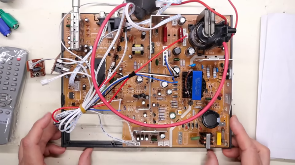
While browsing AliExpress from his digital basement, [Adrian Black] stumbled upon what seemed like a brand-new mainboard for a CRT television set. He decided to take a gamble and ordered one. It finally arrived, and was indeed a brand new product from 2023.

DIGITAL MAIN BOARD OF TV, Work ath [sic] HONGXUN products with the care and precision of a sculptor in each step, wonderful have no limits

CRT Mainboard Transplant in Progress

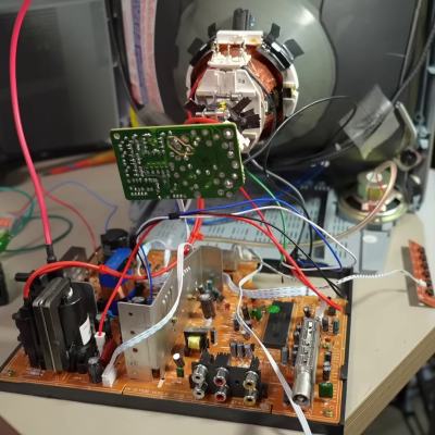
Dubious marketing descriptions like “High Definition Digital Color TV Driver Board” aside, this turned out to be a fairly well-designed analog TV board. [Adrian] pulls a 20-year-old Magnavox ( Philips ) color television set from storage and begins the transplant operation. One interesting observation is the Magnavox board has almost the same layout as the new board, except for the orientation of the sections. The new CRT neck board had a different connector than the Magnavox set, but was designed to accept multiple sized sockets. [Adrian] just removed the new socket and replaced it with one from the old set. The mechanical issues were a bit more complicated, but nothing that a Dremel tool and a bit of hot glue can’t fix. The 220 VAC power supply was eventually modified to accept 110 VAC, which also enabled him to reconnect the degaussing coil.

[Adrian] has collected some relevant documentation in this GitHub repository, including schematics. Why bother with this at all? Well, until now, he didn’t have any way to test / view PAL RF signals in his lab. He was gambling on the new mainboard having a PAL tuner. It does, but as an unadvertised bonus, it supports NTSC and SECAM as well — but still not “HD digital color TV”, as far as we know. If you want a multi-standard TV in your lab, this solution may be worth considering. It appears there is still a market somewhere for new CRT televisions. If you have any background on this, please let us know down below in the comments.

Continue reading “New Motherboard Improves Old CRT Television”

Home Network Organization Gets Out Of Hand

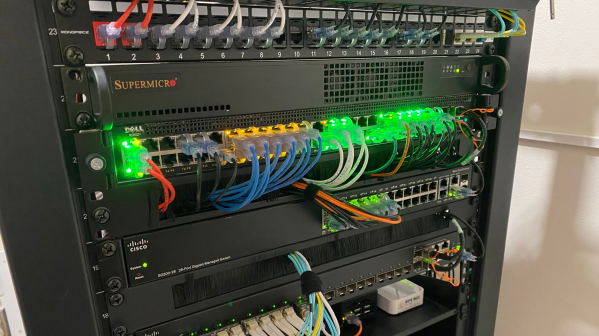
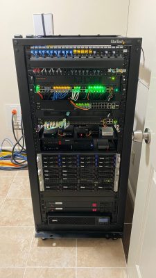
[SpookyGhost] has a big home network, and has taken cable management and server organization to the extreme. He has written about individual components before, but this blog post brings it all together and reviews the entire system. The networking gear is installed in a closet and mounted in a 25U tall 19-inch rack. From top to bottom, here is a brief list of the gear:

Full View of Network Equipment Rack
  • Keystone patch panels
  • pfSense Firewall / Router
  • Two Cisco Ethernet switches
  • Redundant internet connections
  • Shelf of numerous servers
  • RAID-Z2, 12 each 8 TB SCSI, media storage
  • NAS RAID, 6 ea 4 TB SAS, 2 ea 800 GB SSD
  • Video Management System, 48 TB storage
  • UPS and power distribution units

Most of the Ethernet uses 10GBASE-T and Cat6 cabling and connectors, with some interconnects use fiber optical cable and LC connectors. Unsurprisingly, as this setup grew and grew, [spooky] had to pipe in air-conditioning to the closet.

This is a serious installation, but there are plenty of good ideas for folks with less ambitious networking goals and/or requirements. We liked the swappable Keystone jacks in the patch panels, and the cable pass-through panel with a dense curtain of rubber fringe to keep things looking tidy. If you have any ideas to share on network equipment and cable management, let us know in the comments.

Portable 1990s POS Will Strain Your Back

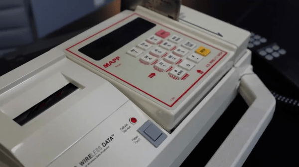
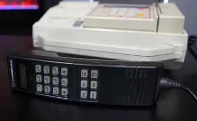
[JR] over at [Tech Throwback] got ahold of an unusual piece of gear recently — a portable Point of Sale (POS) credit card machine from the late 1990s (video, embedded below the break ). Today these machines can be just a small accessory that works in conjunction with your smart phone, but only the most dedicated merchants would lug this behemoth around. The unit is basically a Motorola bag phone, a credit card scanner, a receipt printer, a lead-acid battery, and a couple of PCBs crammed into a custom carrying case

Handset Detail

Despite having a lot of documentation, [JR] struggles to find any information on this U.S. Wireless POS-50. He finds that the credit card scanner is an Omron CAT-95 authorization terminal, and the Motorola SCN-2397B phone appears to come from the Soft-PAK series.

He is able to power it up, but can’t do much with is because he is missing the authorization password. But regardless, with the demise of the Advanced Mobile Phone System for over a decade, this 850 MHz band analog phone can’t connect to the network anymore.

If you happen to know anything about this old POS, or used a similar luggable system for accepting credit cards in the 1990s, let us know in the comments below.

Continue reading “Portable 1990s POS Will Strain Your Back”

Modern Demo For A Casio PB-700 Pocket Computer Plotter

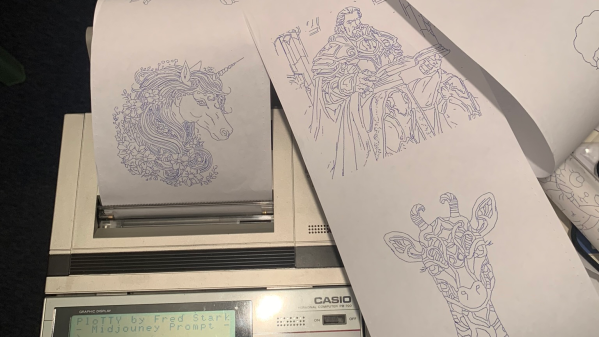
[Fred] has a Casio PB-700 pocket calculator / computer, complete with the companion docking station featuring a four-color pen plotter, model FA-10, and a microcassette tape recorder, model CM-1. He really wanted to see what this plotter could do, but there were no demos that he could find. So despite only having one working pen, [Fred] took matters into his own hands and proceeded to make his own.

What if I made a program where I type what I want to draw and the PB-700 just draws it?

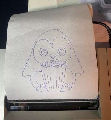
Penguin from Penguindrum eating Popcorn

[Fred] succeeds, shoehorning several sub-projects into a single convoluted work flow: request an image from the PB-700 and after a long pause the plot emerges. The cute microcassette recorder is too much of a hassle, so he emulates the audio interface on a PC using a utility called casutil that reads and writes .wav files in PB-700 format. Much of his effort is spent figuring out how to request an image from Midjourney without being banned, but eventually comes up with a workable but shaky solution. The last steps are to convert the image into a line drawing, and then wrap up all those X-Y coordinates into a Basic program and send it back down to the PB-700 for plotting.

You can read more details in the PloTTY GitHub repository. There were several of these pocket computers with plotters coming out of Japan in the 1980s. In addition to this Casio, the Radio Shack TRS-80 PC-1 and PC-2 come to mind, which were re-branded versions of the Sharp PC-1211 and PC-1500 models. We wrote about them last year. This author had a PC-2 in 1985 and used it to plot antenna patterns at his desk, bypassing the IT department’s red tape. Have you ever used any of these pocket plotters? If so, let us know in the comments below. Thanks to [Altomare] for send us the tip.

Opening A Curta — With Great Care

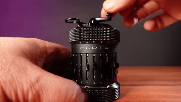
We’ve always admired Curta mechanical calculators, and would be very hesitant to dismantle one. But [Janus Cycle] did just that — and succeeded. A friend sent him a Curta Model 2 calculator that was frozen up. Just opening the case involved percussive force to remove a retaining pin, and once inside he discovered the main shaft had been slightly bent. No doubt this calculator had suffered a drop at some point in the past.

I’m sticking to the rule of doing no harm — I’d rather not be able to fix this than do something that causes more problems.

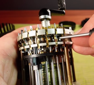
Inside the Curta

But surprisingly, he was able to get it substantially back in working order without completely taking apart all 600+ parts. Most of the issues were shafts whose lubrication had become gummy, and one carry lever was slightly bent. There is still a little more work, but soon this calculator will once again be cranking out results.

Has anyone dismantled a mechanical contraption this complicated before, for example a teletype machine? Let us know in the comments. If you want to brush up on your Curta knowledge, check out the Curta Calculator Page. We also wrote a Retrotechtacular about the Curta before. Thanks to [mister35mm] for sending in this tip.

Continue reading “Opening A Curta — With Great Care”