HP 3488A Teardown, Dismantled For Parts

[IMSAI Guy] has an old HP 3488A Switch Control Unit that he wants to dismantle for parts ( see video below the break ). The 3488A is pretty simple as far as HP test equipment goes — a chassis that can hold various types of relay cards and is programmable over GPIB. He notes up front that these are plentiful and inexpensive in the used test equipment market. Continue reading “HP 3488A Teardown, Dismantled For Parts”

Hack Your Heathkit To Trace MOSFET Curves

[TRX Lab] has an old Heathkit model IT-1121 curve tracer, and wants to modify it so he can plot the I-V curves of MOSFETs. For the uninitiated, curve tracers are used to determine the precise characteristics of components by measuring the output for a set of specific inputs – either voltage or current depending on the device you’re testing.

The IT-1121 was introduced in 1973 and supports bipolar and FET transistors of types NPN, PNP, N-channel, and P-channel, along with various other semiconductor devices. But [TRX] wanted to enhance the tester to deal with MOSFETs as well.

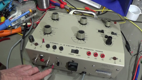
The IT-1121 is very flexible, and has selector switches for all the usual polarity and sweep settings — Heathkit also sold a model IT-3121 in later years, but this seems to have been the same basic tester. [TRX] found two shortcomings when plotting the I-V curve of MOSFETs. First, there is no way to apply a Vgs threshold voltage to the curves. Second, when set for FET testing, the polarity of the gate voltage stair step waveform doesn’t match the desired polarity of the drain-source voltage.

In the video below the break, [TRX] first walks us through some of the reasons you’d want a curve tracer in your lab. In the next part of the video, he breadboards up the modification for testing, and finally buttons it up and installs it. Implementing the modification was pretty straightforward. [TRX] designed four op-amp circuit that adds the adjustable offset and a switch to toggle the polarity of the gate voltage waveform. The whole thing fits on a small breadboard inside the case. Two holes are drilled in the panel for the potentiometer and switch.

There’s no GitHub repository for this project, but he presents the full details in the video and says viewers are free to make snapshots of the schematics and layout if they want to build their own.

Modern I-V curve tracers are pretty pricey. Even used, decades-old professional curve tracers are above the budget of most home and small office labs. If you have, or can get one of these at a decent price, this would be a modification well worth considering. You might also consider a home-brew tracer, like this one we covered last year.

Continue reading “Hack Your Heathkit To Trace MOSFET Curves”

Cornell Updates Their MCU Course For The RP2040

The School of Electrical and Computer Engineering at Cornell University has made [Bruce Land]’s lectures and materials for the Designing with Microcontrollers (ECE 4760) course available for many years. But recently [Bruce], who semi-retired in 2020, and the new lecturer [Hunter Adams] have reworked the course and labs to use the Raspberry Pi Pico. You can see the introductory lecture of the reworked class below.

Not only are the videos available online, but the class’s GitHub repository hosts extensive and well-documented examples, lecture notes, and helpful links. If you want to get started with RP2040 programming, or just want to dig deeper into a particular technique, this is a great place to start.

From what we can tell, this is the third overhaul of the class this century. Back in 2012 the course was using the ATmega1284 AVR microcontroller, and in 2015 it switched to the Microstick II using a Microchip PIC32MX. Not only were these lecture series also available free online, but each has been maintained as reference after being replaced. One common thread with all of these platforms is their low cost of entry. Assuming you already have a computer, setting up the hardware and software development environment for these modules costs less than the price of a pizza dinner, a fact no doubt appreciated by the ECE department’s budget director.

We’ve covered this course before back in 2015 when it first changed. Another free online course on embedded system design is from [Prof James Conrad] at UNC Charlotte, based on the Renasas RX63N microcontroller — the UNC Charlotte team drove development of the autonomous vehicle project we covered back in 2009. If you know of other online embedded systems classes, let us know in the comments below.

Continue reading “Cornell Updates Their MCU Course For The RP2040”

Physics-Controlled Component Auto-Placer

[Jarrett] recently stumbled upon a class of drawing algorithms called force-directed graphs, which artificially apply forces to the elements. The final graph is then generated by applying the laws of physics and letting the system reach equilibrium. This can often result in a pleasing presentation of things like mind maps and other diagrams without having to hand-place everything. He realized that this approach almost mimics the way he places components when doing a PCB layout. Out of curiosity or intense boredom, we’re not sure which, he decided to implement this in a tool that interacts with KiCad ( see animated GIF below the break ).

He has to ignore certain nets such as power and ground rails, because they distort the result. This simulation treats the nets as springs, and the center of each footprint behaves a charged particle. [Jarrett] added a twist, literally, to the usual implementations — each net pulls on its pin, not the part center, and therefore the chips will both rotate and be pushed around as the system stabilizes.

The results are sometimes quite striking. Useful? Dubious, but maybe!

The project code is up on GitHub, but is very experimental and he is unlikely to carry it further. Among the missing features, the Python code must be tweaked for each different netlist files and other parameters, and there is no way to feed the result back into KiCad. But this is enough for [Jarrett], who only set out to see if the concept was possible. The code is available if anyone wants to try their hand at taking this to the next level.

Continue reading “Physics-Controlled Component Auto-Placer”

Stepper Killer Killer Killed, Repair Attempted

The low-cost servo motor in [Clough42]’s lathe’s electronic leadscrew bit the dust recently, and he did a great job documenting his repair attempts ( see video below the break ). When starting the project a few years ago, he studied a variety of candidate motors, including a ClearPath servo motor from Teknic’s “Stepper Killer” family. While that motor was well suited, [Clough42] picked a significantly lower-cost servo motor from China which he dubbed the “Stepper Killer Killer”.

He does a very thorough post-mortem of the motor’s integrated servo controller, checking the circuits and connections on the interface PCB first. Not finding any obvious problem, he proceeds to the main PCB which contains the microcontroller, motor driver transistors, and power supplies. There is no visible damage, but a check of the logic power supply shows 1.65V where 3.3V is expected. Looking at the board with a smart-phone mounted IR camera, he quickly finds the bad news — the microcontroller has shorted out.

Continue reading “Stepper Killer Killer Killed, Repair Attempted”

A Close Look At How Flip-Dot Displays Really Work

[Mike Harrison] has an upcoming project which will combine a large number of flip-dot displays salvaged from buses. [Mike] thought he knew how these things worked, and had a prototype PCB made right away. But while the PCB was being manufactured, he started digging deeper into the flip-dot’s flipping mechanism.

As he dismantled one of the flip-dots, he realized there was a lot going on under the hood than he realized. The dots are bistable — staying put when power is removed. This is achieved with a U-shaped electromagnet. The polarity of a driving pulse applied to the coil determines which way to flip the dot and saturates the electromagnet’s core in the process. Thus saturated, each dot is held in the desired position because the black side of the dot is made from magnetic material. But wait, there’s more — on further inspection, [Mike] discovered another permanent magnet mounted in the base. He’s not certain, but thinks its job is to speed up the flipping action.

Besides curiosity, the reason [Mike] is studying these so closely is that he wants to build a different driver circuit to have better and faster control. He sets out to better understand the pulse waveform requirements by instrumenting a flip-dot and varying the pulse width and voltage. He determines you can get away with about 500 us pulses at 24 V, or 1 ms at 12 V, much better that the 10 ms he originally assumed. These waveforms result in about 60 to 70 ms flip times. We especially enjoyed the slow-motion video comparing the flip at different voltages at 16:55 in the video after the break.

[Mike] still has to come up with the optimum driving circuit. He has tentatively has settled on a WD6208 driver chip from LCSC for $0.04/ea. Next he will determine the optimum technique to scale this up, deciding whether going for individual pixel control or a multiple sub-array blocks. There are mechanical issues, as well. He’s going to have to saw off the top and bottom margin of each panel. Reluctant to unsolder the 8500+ joints on each panel, his current idea is to solder new controller boards directly onto the back of the existing panels.

This video is a must-watch if you’re working on drivers for your flip-dot display project, and we eagerly look forward to any future updates from [Mike]. We also wrote about a project that repurposed similar panels a couple of years ago. There are a few details that [Mike] hasn’t figured out, so if you know more about how these flip-dots work, let us know in the comments below.

Continue reading “A Close Look At How Flip-Dot Displays Really Work”

Collection Of Old Films Rescued For Preservation

Periscope Film owners [Doug] and [Nick] just released a mini-documentary about the rescue of a large collection of old 35 and 16 mm celluloid films from the landfill. The video shows the process of the films being collected from the donor and then being sorted and organized in a temporary storage warehouse. There is a dizzying variety of films in this haul, from different countries, in both color and black and white.

We can see in the video that their rented 8 meter (26 foot) cargo truck wasn’t enough to contain the trove, so they dragged along a 1.8 x 3.6 m (6 x 12 ft) double-axle trailer as well. That makes a grand total of 49 cubic meters of space. Our back-of-the-envelope calculations says that filled to the brim, that would be over 30,000 canisters of 600 m (2,000 ft) 35 mm movie reels.

When it comes to preserving these old films, one big problem is physical deterioration of the film stock itself. You will know something is wrong when you get a strong acetic or vinegary odor when opening the can. [Nick] shows some examples where the film has even become solidified, taken on a hexagonal shape. It will take months to just assess and catalog the contents of this collection, with damaged films that are still salvageable jumping to the head of the queue to be digitized.

Film Scanning Artist [Esteban] Performing Color Correction
Films are digitized at 4K resolution using a Lasergraphics ScanStation archival quality film scanning system, and then the restoration fun begins. One issue demonstrated in this video is color deterioration. In the Eastmancolor film technology introduced in the 1950s, the blue dyes deteriorate over time. This, and a plethora of other issues, are corrected in the restoration process.

We’re particularly jealous of film scanning artist [Esteban]’s triple-headed trackball. We learned from a quick Google search this beast is merely the entry level control panel from UK company Tangent — they make even larger flavors.

If you’re interested in doing this with 8 mm home movies, we covered a project way back in 2011 of a DIY home movie scanning project. We also covered one of Periscope Film’s restored training films about NASA soldering techniques from 1958. Kudos to organizations who focus on keeping these types of interesting and historical films from being dumped in the landfill and lost forever.

Continue reading “Collection Of Old Films Rescued For Preservation”