Dumping 90’s Honda ECU Programming With Arduino

[P1kachu] owns a pair of early 1990’s Honda’s with custom tuning on their stock ECUs, and after having to get the ECU repaired on his ’93 civic, he found himself going down the rabbit hole of Honda ECU EPROM chips.

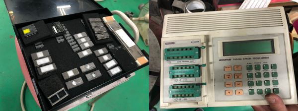
During the repair process, the tuning shop owner, or [Tuner-san] as [P1ikachu] refers to him, made a backup of the custom tuning to another EPROM chip.  This was done with an old Advantest R4945A EPROM programmer, which [Tuner-san] supposedly also used to clone Famicom cartridges back in the day. After realizing that [Tuner-san] could only clone the contents, but not view or modify it, he started looking at ways to do that.

EPROMS are programmed using higher voltage (12.5 V – 25 V) but to read them 5 V is used. The memory address is selected by setting each of the 15 address pins high or low, and then reading the status of the 8 data pins to extract one byte of data. Rinse and repeat for each of the 256 memory addresses on the Microchip 27C256 EPROM. One of the previous owners of [Pikachu]’s Civic made some unknown tuning changes, so he is in the process of looking at the dumped data to see what was changed. Once he has completed figuring out the programming table of the EPROM, he plans to do some testing with [Tuner-san] to possible smooth out the rev limited.

An interesting aspect of EPROMs is that they are erased using UV light, which sets all the memory bits to 1. During programming, selected bits can be set to 0, but it’s not possible to set them back to 1 without erasing the entire chip again.

Messing around with the computers in cars is not only for tuning, but can also expose some rather serious security flaws, especially in modern vehicles.

Sub-mm Mechanical 3D Scanner With Encoders And String

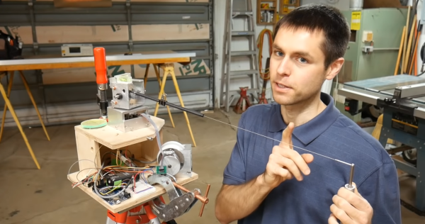
[Scott Rumschlag] wanted a way to precisely map interior spaces for remodeling projects, but did not want to deal with the massive datasets created by optical 3D scanning, and found the precision of the cost-effective optical tools lacking. Instead, he built a 3D cable measuring device that can be used to map by using a manual probe attached to a cable.

The cable is wound on a retractable spool, and passes over a pulley and through a carbon fiber tube mounted on a two-axis gimbal. There are a few commercial machines that use this mechanical approach, but [Scott] decided to build one himself after seeing the prices. The angle of rotation of each axis of the gimbal and the length of extended cable is measured with encoders, and in theory the relative coordinates of the probe can be calculated with simple geometry. However, for the level of precision [Scott] wanted, the devil is in the details. To determine the position of a point within 0.5 mm at a distance of 3 m, an angular resolution of less than 0.001° is required on the encoders. Mechanical encoders could add unnecessary drag, and magnetic encoders are not perfectly linear, so optical encoders were used. Many other factors can also introduce errors, like stretch and droop in the cable, stickiness of the bearings, perpendicularity of the gimbals axis and even the spring force created by the encoder wires. Each of these errors had to accounted for in the calculations. At first, [Scott] was using an Arduino Mega for the geometry calculations, but moved it to his laptop after he discovered the floating point precision of the Mega was not good.

[Scott] spend around 500 hours building and tuning the device, but the end result is really impressive. There are surprisingly few optical machines that can achieve this level of precision and accuracy, and they can be affected by factors like the reflectivity of an object.

If you do want to get into real 3D scanning, definitely take the time to read [Donal Papp]’s excellent guide to the practical aspects of the various technologies. Most of us already have a 3D scanner in our pocket in the form of a smartphone, which can be used for photogrammetry.

Continue reading “Sub-mm Mechanical 3D Scanner With Encoders And String”

PinThing Mechanizes Pin Art

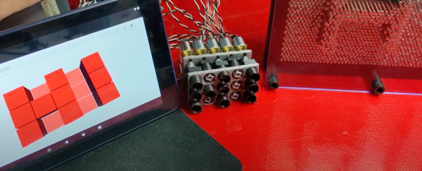
Pin art is one of those things that simply cannot be left alone if it’s within arms reach, and inevitably end up with a hand or face imprint. [hugs] is also fascinated by them, so he designed the PinThing, a mechanized pin art display.

The PinThing pin diameters are much larger than standard pin art, but this is to fit small geared DC motors. Each pin is a short 3D-printed lead screw mechanism. The motors are driven with a stack of motor driver shields on top of an Arduino Uno, which uses Firmata to receive instructions over serial from a Node.js app using the Johnny-Five library. This may be a simple 3×5 proof of concept, but then it could be used for everything from displays to interactive table surfaces.

One of the challenges with pixelated mechanical displays like this, the inFORM from MIT, or even flip dot displays, are the costs in actuators and driver electronics. A small 10×10 array requires 100 motors and drivers, which quickly adds up as you expand, even if individual components are quite cheap.

If you are willing to sacrifice instantaneous response from each pixel, you can use a mechanical multiplexer. It consists of some sort of moving carriage behind the display with mounted actuators, so you’ll only need an actuator per row, not for every pin. This also means the pins can be closer together since the actuators can be staggered on the carriage.

PinThing project was an entry to the Rethink Displays Challenge of the 2021 Hackaday Prize, for which the finalists were just announced.

Continue reading “PinThing Mechanizes Pin Art”

The Incredible Mechanical Artistry Of François Junod

The art of building purely mechanical automatons has dramatically declined with the arrival of electronics over the past century, but there are still a few craftsmen who keep the art form alive. [François Junod] is one of these masters, and the craftsmanship and intricacy on display in his automata is absolutely amazing.

[François]’ creations are all completely devoid of electronics, and are powered either by wound-up springs or weights. The mechanics of the automata are part of the display, and contain a vast array of gears, linkages, belts and tracks. Many of them also include their own soundtrack, which range from simple bells and chimes to complete melodies from mechanized wind instruments, as demonstrated in Le Champignonneur below. He also collaborates with craftsman like jewelers on works like La Fée Ondine, which we thought was CGI when we first saw it in the video after the break.

Very few people have the time, skill and patience to make these creations, but we are glad there are still a few around. Some builds, like [Patelo]’s flightless drone aren’t quite as complex, but are no less inspiring. If you don’t quite have the time and fabrication skills, you can still create mesmerizing automatons with 3D printing like [gzumwalt]. Continue reading “The Incredible Mechanical Artistry Of François Junod”

Ball CVT Drives Robot From A Constant Speed Motor

[James Bruton] is experimenting is a series of interesting mechanical mechanisms, the latest being a CVT transmission system which uses a tilting sphere to get a variable speed output from a constant speed input. Video after the break.

In [James]’ proof of concept RC vehicle, a single powered disc is mounted on top, at 90 degree to the wheels. A rotating sphere makes contact with both the driven disc and the wheel. When the rotation axis of the sphere is at 45° between the disc and the wheel, it provides a one 1:1 transmission ratio. As the axis is tilted, the contact points on the sphere shift, changing the relative circumference at the contact points, and therefore changing the transmission ratio. It can also reverse by tilting the sphere in the opposite direction, and disconnected from the output wheel by aligning it with the hole in the bottom of the sphere. [James]’ simple two-wheel RC car concept quite well, driving around his kitchen with the transmission spheres being tilted by servos.

Thanks to the response time, CVT gearboxes are generally not needed for electric motors, but on internal combustion engines that which run best within a certain RPM range they can be very useful. One possible weak point of a design like this is it’s dependence on friction to transfer torque, which makes it vulnerable to wear and slipping.

This build is a spin-off of his spherical omni-wheels and the robot chassis he developed around them. For another interesting robot mechanism, check out is gyroscope balancing system. Continue reading “Ball CVT Drives Robot From A Constant Speed Motor”

PetBot: Turn PET Bottles Into Filament

Recycling plastic into filament normally involves chopping it into tiny pieces and pushing it through a screw extruder. [JRT3D] is taking a different approach with PetBot, which cuts PET bottles into tape and then turns it into filament. See the videos after the break.

Cutting the tape and extrusion happens in two completely separated processes on the same machine. A PET bottle is prepared by cutting off the bottom, and the open rim is pushed between a pair of bearings, where a cutter slices the bottle into one long strip, as a driven spool rolls it up. The spool of tape is then moved to the second stage of the machine, which pulls the tape through a hot end very similar to that on a 3D printer. While most conventional extruders push the plastic through a nozzle with a screw, the PetBot only heats up the tape to slightly above its glass transition temperature, which allows the driven spool to slowly pull it through the nozzle without breaking. A fan cools the filament just before it goes onto the spool. The same stepper motor is used for both stages of the process.

We like the simplicity of this machine compared to a conventional screw extruder, but it’s not without trade-offs. Firstly is the limitation of the filament length by the material in a single bottle. Getting longer lengths would involve fusing the tape after cutting, or the filament after extrusion, which is not as simple as it might seem. The process would likely be limited to large soda bottle with smooth exterior surfaces to allow the thickness and width of the tape to be as consistent as possible. We are curious to see the consistency of the filaments shape and diameter, and how sensitive it is to variations in the thickness and width of the tape. That being said, as long as you understand the limitations of the machine, we do not doubt that it can be useful. Continue reading “PetBot: Turn PET Bottles Into Filament”

Listen To The RF Around You

These days, we are spoiled for choice with regard to SDRs for RF analysis, but sometimes we’re more interested in the source of RF than the contents of the transmission. For this role, [Drew] created the RFListener, a wideband directional RF receiver that converts electromagnetic signal to audio.

The RF Listener is built around a AD8318 demodulator breakout board, which receives signals using a directional broadband (900 Mhz – 12 Ghz) PCB antenna, and outputs an analog signal. This signal is fed through a series of amplifiers and filters to create audio that can be fed to the onboard speaker. Everything is housed in a vaguely handgun shaped enclosure, with some switches on the back and a LED amplitude indicator. [Drew] demonstrates the RFListener around his house, pointing it at various devices like his router, baby monitor and microwave. In some cases, like with a toy drone, the modulation is too high frequency to generate audio, so the RF listener can also be switched to “tone mode”, which outputs audio tone proportional to the signal amplitude.

The circuit is completely analog, and the design was first done in Falstad Circuit Simulator, followed by some breadboard prototyping, and a custom PCB for the final version. As is, it’s already an interesting exploration device, but it would be even more so if it was possible to adjust the receiver bandwidth and frequency to turn it into a wideband foxhunting tool.