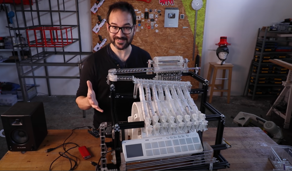
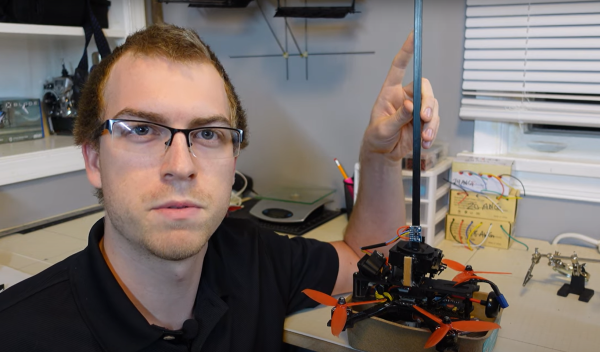
Slick Keyboard Built With PCB Magic

Sometimes a chance conversation leads you to discover something cool you’ve not seen before, and before you know it, you’re ordering parts for yet another hardware build. That’s what happened to this scribe the other day when chatting on some random discord, to QMK maintainer [Nick Brassel aka tzarc] about Djinn, a gorgeous 64-key split mechanical keyboard testbed. It’s a testbed because it uses the newest STM32G4x microcontroller family, and QMK currently does not have support for this in the mainline release. For the time being, [Nick] maintains a custom release, until it gets merged.

Hardware-wise, the design is fabulous, with a lot of attention to detail. We have individual per-key RGB LEDs, RGB underglow, a rotary encoder, a five-way tactile thumb switch, and a 240×320 LCD per half. The keyboard is based on a three PCB stack, two of which are there purely for structure. This slick design has enough features to keep a fair few of us happy.

Interestingly, when you look at the design files (KiCAD, naturally) [Nick] has chosen to take a mirrored approach to the PCB. That means the left and right sides are actually the same PCB layout. The components are populated on different sides of the PCB depending on which half you’re looking at! By mirroring footprints on both PCB sides, and hooking everything up in parallel, it’s possible to do it all with a single master layout.

This is a simple but genius idea that this scribe hadn’t come across before (the shame!) Secondarily it keeps costs down, as your typical Chinese prototyping house will not deal in PCB quantities below five, so you can make two complete keyboards on one order, rather than needing two orders to make five. (Yes, there are actually three unique PCBs, but we’re simplifying the situation, ok?)

Now, if only this pesky electronics shortage could abate a bit, and we could get the parts to build this beauty!

Obviously, we’ve covered many, many keyboards over the years. Here’s our own [Kristina’s] column all about the things. If you need a little help with your typing skills, this shocking example may be the one for you. If your taste is proper old-school clackers, there’s something for everyone.

Polymer Discovery Gives 3D-printed Sand Super Strength

Research activity into 3D printing never seems to end, with an almost constant stream of new techniques and improvements upon old ones hitting the news practically daily. This time, the focus is on a technique we’ve not covered so much, namely binder jetting additive manufacturing (BJAM for short, catchy huh?) Specifically the team from Oak Ridge National Laboratory, who have been exploring the use of so-called hyperbranched Polyethyleneimine (PEI) as a binder for jetting onto plain old foundry silica sand (nature, free access.)

Roll, spray, bake. Simples.

The PEI binder was mixed with a 75:25 mix of water and 1-propanol (not to be mixed up with 2-propanol aka isopropanol) to get the correct viscosity for jetting with a piezoelectric print head and the correct surface tension to allow adequate powder bed penetration, giving optimal binding efficiency. The team reported a two-fold increase in strength over previous jetting techniques, however, the real news is what they did next; by infusing the printed part (known as the green part) with common old ethyl cyanoacrylate (ECA, or super glue to us) the structural strength of the print increased a further eight times due to the reaction between the binder and the ECA infiltrate.

To further bestow the virtues of the PEI binder/ECA mix, it turns out to be water-soluble, at least for a couple of days, so can be used to make complex form washout tooling — internal supports that can be washed away. After a few days, the curing process is complete, resulting in a structure that is reportedly stronger than concrete.  Reinforce this with carbon fiber, and boy do you have a tough building material!

Not bad for some pretty common materials and a simple printing process.

We covered a similar binder jetting process for using sawdust a little while ago, and a neat way of printing with metal powder by carrying it in a stream of argon and cooking it with a laser, but there is an opening for a DIY effort to get in on the binder jetting game.

Thanks [Victor] for the tip!

Isolated Oscilloscope Design Process Shows How It’s Done

[Bart Schroder] was busy designing high voltage variable speed motor drives and was lamenting the inability of a standard scope to visualise the waveforms around the switch transistors. This is due to the three phase nature of such motors being driven with three current waveforms, out of phase with each other by 120 degrees, where current flows between each pair of winding taps, without being referenced to a common notion of ground. The average scope on your bench however, definitely is ground-referenced, so visualising such waveforms is a bit of a faff. Then there’s the fact that the motors run at many hundreds of volts, and the prospect of probing that with your precious bench instrument is a little nerve-wracking to say the least. The solution to the issue was obvious, build your own isolated high voltage oscilloscope, and here is the Cleverscope CS448 development journey for your viewing pleasure.

The scope itself is specification-wise nothing too flash, it’s the isolated channels that make it special. It does however have some niceties such as an extra eight 100 Mbps digital inputs and a handy 65 MHz signal generator. Also, don’t reach for your wallets just yet, as this is a specialised instrument with an even smaller potential user base than a normal scope, so these units are rather pricey. That all said, it’s not the existence of the scope that is the focus here, it’s the journey from problem to solution that interests us the most. There is much to learn from [Bart’s] journey, for example, where to place the frontend ADC? Isolated side or not? The noise floor of the signal chain dictated the former.

Continue reading “Isolated Oscilloscope Design Process Shows How It’s Done”

3D Printed Marble Music Machine Looking Good Already

Inspired by the enormous marble music machines from the staggeringly talented [Wintergatan] and the marble run builds by [Daniel de Bruin], [Ivan Miranda] has been busy again building a largely 3D printed contraption to test his ideas around building his own marble music machine from scratch. (Video, embedded below.)

Leveraging his recent experiences with resin printing and his own giant 3D printer, he had no difficulty in producing everything he needed from his workshop, even if the design work apparently took ages.

The build shows how early in development this project is, as there are clearly quite a few issues to be dealt with, but progress looks encouraging so far. To be clear, plans are to ‘go big’ and this little eight-channel testbed is just to explore this issues around ball guiding, transport and ball release onto the first audio test device, a Korg Nano Pad 2.

Some significant teething problems were identified, such as when [Ivan] designed the ball lifter, he intended the balls to load from the rear, but then needed to switch it to load from the front. No big deal, simply reverse the motor direction to load balls on the opposite side of the mechanism. Sadly, that also meant the directly coupled note drum was now also rotating the wrong way to release the balls. Oops. A quick hack later and [Ivan] was back in business. Various parts needed shimming up with plates, but with 3D printers on the bench, knocking those out took little time or effort. This just shows how darn useful 3D printers can be, allowing you to iterate in a short time and feed your hacks back into the final version.

[Ivan] is clearly going to have a lot of ‘fun’ with this one, as [Wintergatan] will surely testify, these big musical marble machine builds are quite some undertaking. We shall definitely be tuning in later on to see where this one goes!

While we’re on the subject of the [Wintergatan] marble machines, here’s a mini homage to the latest Marble Machine X, and if you’re in the need for a 3D printed marble clock, then try this one for starters.

Continue reading “3D Printed Marble Music Machine Looking Good Already”

Designing Electronics That Work

[Hunter Scott] who has graced these pages a fair few times, has been working on electronics startups for the past ten years or so, and has picked up a fair bit of experience with designing and building hardware. Those of us in this business seem to learn the same lessons, quite often the hard way; we call it experience. Wouldn’t it be nice to get up that learning curve a little quicker, get our hardware out there working sooner with less pain, due to not falling into the same old traps those before us already know about? The problem with the less experienced engineer is not their lack of talent, how quickly they can learn, nor how much work they can get done in a day, but simply that they don’t know what they don’t know. There’s no shame in that, it’s just a fact of life. [Hunter] presents for us, the Guide to Designing Electronics that Work.

The book starts at the beginning. The beginning of the engineering process that is; requirements capturing, specifications, test planning and schedule prediction. This part is hard to do right, and this is where the real experience shows. The next section moves onto component selection and prototyping advice, with some great practical advice to sidestep some annoying production issues. Next there’s the obvious section on schematic and layout with plenty of handy tips to help you to that all important final layout. Do not underestimate how hard this latter part is, there is plenty of difficulty in getting a good performing, minimal sized layout, especially if RF applications are involved.

The last few sections cover costing, fabrication and testing. These are difficult topics to learn, if up till now all you’ve done is build prototypes and one-offs. These are the areas where many a kickstarter engineer has fallen flat.

Designing Electronics That Work doesn’t profess to be totally complete, nor have the answer to everything, but as the basis for deeper learning and getting the young engineer on their way to a manufacturable product, it is a very good starting point in our opinion.

The book has been around a little while, and the latest version is available for download right now, on a pay what-you-want basis, so give it a read and you might learn a thing or two, we’re pretty confident it won’t be time wasted!

Is This 12-layer PCB Coil The Next Step In Ferrofluid Displays?

[Applied Procrastination] is in the business of vertical ferrofluid displays, but struggles somewhat with the electromagnets available off the shelf and the proliferation of wiring that results. [Carl Bugeja] is in the business of making PCB coils, both with rigid and flex PCB substrates, so when the opportunity for a collaboration arose, [AP] jumped at the opportunity.

As [Simen from AP] mentions in the video after the break, they had considered using a large PCB with embedded coils for Fetch their ferrofluid display unit, but the possible magnetic field was just too weak, and attempting to crank up the amps, just overheats them. Some improvements were made, first sticking the coil PCB to a small disk of ferrous metal, which doubled up as a handy heatsink. Next, he tried adding a permanent magnet, which added a bit of bias field. Alone this was not enough to hold the ferrofluid in place, but with the coil powered, it was starting to look encouraging.

Much more progress was made when [Carl] sent over a new design of his, a 12-layer PCB coil. This obviously had a much larger field, but still not enough without the extra boost from permanent magnet.

[Simen] currently doesn’t think the PCB approach is quite there yet, and is looking for help to source PCB-mounted electromagnets of the wired variety. We would imaging prototyping with such a large 12-layer PCB would be rather prohibitively expensive anyway.

Continue reading “Is This 12-layer PCB Coil The Next Step In Ferrofluid Displays?”

Hacked Punch-Out Controlled With Actual Punches

In a slightly safer departure away from jetpack roller-skating and flinging around bolts of lightning, [Ian Charnas] has been hacking retro video games. After a lot of hard work [Ian] has managed to add pose estimation to control the character in the NES boxing game “Punch-Out.” Surely he can’t get hurt doing that? No, but since it wasn’t fair to hurt the poor suffering characters, without taking any damage himself, he added electric-shock feedback to give the game a bit more, ahem, punch. See, you can get hurt playing video games!

By starting with Google MoveNet, which is a pre-baked skeletal tracking model which can run in a browser using TensorFlowJS, he defined some simple heuristics for the various boxing moves usually performed with the game controller. Next, he needed to get the game. Being a all-round good guy, [Ian] bought an original copy of the game cartridge to obtain the license, then using the USB CopyNES from RetroUSB, dumped out the game binary for the next step.

Emulation of the NES hardware was chosen, taken care of by FCEUX, in order to run the game and the posture model on the same machine. This simplified the control of the game, since it would be somewhat more work to have it run on the original NES. By using emscripten, FCEUX was cross-compiled to WebAssembly, and so both the game and control side are both in the land of JavaScript. To be honest, after playing the game a little, [Ian] found it far too fast to be playable with posture control, as opposed to much faster button pressing, so some game hacking was required. Emulation made this much easier.

It took [Ian] around two months of disassembling the game binary, and figuring out the game logic around the characters in order to slow them down enough to make it playable, but he did manage it. You can be the judge, since he bought a bunch more cartridges to unlock more license copies, you can play it too. Just don’t add the electric-shock part, nobody needs to be administered electric shock therapy from a two inch high bright orange Mike Tyson!

Continue reading “Hacked Punch-Out Controlled With Actual Punches”