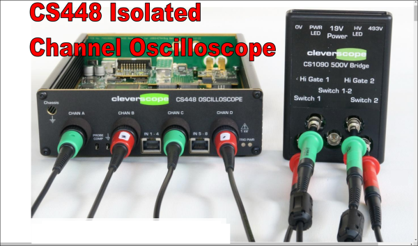
3D Printed Marble Music Machine Looking Good Already

Inspired by the enormous marble music machines from the staggeringly talented [Wintergatan] and the marble run builds by [Daniel de Bruin], [Ivan Miranda] has been busy again building a largely 3D printed contraption to test his ideas around building his own marble music machine from scratch. (Video, embedded below.)

Leveraging his recent experiences with resin printing and his own giant 3D printer, he had no difficulty in producing everything he needed from his workshop, even if the design work apparently took ages.

The build shows how early in development this project is, as there are clearly quite a few issues to be dealt with, but progress looks encouraging so far. To be clear, plans are to ‘go big’ and this little eight-channel testbed is just to explore this issues around ball guiding, transport and ball release onto the first audio test device, a Korg Nano Pad 2.

Some significant teething problems were identified, such as when [Ivan] designed the ball lifter, he intended the balls to load from the rear, but then needed to switch it to load from the front. No big deal, simply reverse the motor direction to load balls on the opposite side of the mechanism. Sadly, that also meant the directly coupled note drum was now also rotating the wrong way to release the balls. Oops. A quick hack later and [Ivan] was back in business. Various parts needed shimming up with plates, but with 3D printers on the bench, knocking those out took little time or effort. This just shows how darn useful 3D printers can be, allowing you to iterate in a short time and feed your hacks back into the final version.

[Ivan] is clearly going to have a lot of ‘fun’ with this one, as [Wintergatan] will surely testify, these big musical marble machine builds are quite some undertaking. We shall definitely be tuning in later on to see where this one goes!

While we’re on the subject of the [Wintergatan] marble machines, here’s a mini homage to the latest Marble Machine X, and if you’re in the need for a 3D printed marble clock, then try this one for starters.

Continue reading “3D Printed Marble Music Machine Looking Good Already”

Designing Electronics That Work

[Hunter Scott] who has graced these pages a fair few times, has been working on electronics startups for the past ten years or so, and has picked up a fair bit of experience with designing and building hardware. Those of us in this business seem to learn the same lessons, quite often the hard way; we call it experience. Wouldn’t it be nice to get up that learning curve a little quicker, get our hardware out there working sooner with less pain, due to not falling into the same old traps those before us already know about? The problem with the less experienced engineer is not their lack of talent, how quickly they can learn, nor how much work they can get done in a day, but simply that they don’t know what they don’t know. There’s no shame in that, it’s just a fact of life. [Hunter] presents for us, the Guide to Designing Electronics that Work.

The book starts at the beginning. The beginning of the engineering process that is; requirements capturing, specifications, test planning and schedule prediction. This part is hard to do right, and this is where the real experience shows. The next section moves onto component selection and prototyping advice, with some great practical advice to sidestep some annoying production issues. Next there’s the obvious section on schematic and layout with plenty of handy tips to help you to that all important final layout. Do not underestimate how hard this latter part is, there is plenty of difficulty in getting a good performing, minimal sized layout, especially if RF applications are involved.

The last few sections cover costing, fabrication and testing. These are difficult topics to learn, if up till now all you’ve done is build prototypes and one-offs. These are the areas where many a kickstarter engineer has fallen flat.

Designing Electronics That Work doesn’t profess to be totally complete, nor have the answer to everything, but as the basis for deeper learning and getting the young engineer on their way to a manufacturable product, it is a very good starting point in our opinion.

The book has been around a little while, and the latest version is available for download right now, on a pay what-you-want basis, so give it a read and you might learn a thing or two, we’re pretty confident it won’t be time wasted!

Is This 12-layer PCB Coil The Next Step In Ferrofluid Displays?

[Applied Procrastination] is in the business of vertical ferrofluid displays, but struggles somewhat with the electromagnets available off the shelf and the proliferation of wiring that results. [Carl Bugeja] is in the business of making PCB coils, both with rigid and flex PCB substrates, so when the opportunity for a collaboration arose, [AP] jumped at the opportunity.

As [Simen from AP] mentions in the video after the break, they had considered using a large PCB with embedded coils for Fetch their ferrofluid display unit, but the possible magnetic field was just too weak, and attempting to crank up the amps, just overheats them. Some improvements were made, first sticking the coil PCB to a small disk of ferrous metal, which doubled up as a handy heatsink. Next, he tried adding a permanent magnet, which added a bit of bias field. Alone this was not enough to hold the ferrofluid in place, but with the coil powered, it was starting to look encouraging.

Much more progress was made when [Carl] sent over a new design of his, a 12-layer PCB coil. This obviously had a much larger field, but still not enough without the extra boost from permanent magnet.

[Simen] currently doesn’t think the PCB approach is quite there yet, and is looking for help to source PCB-mounted electromagnets of the wired variety. We would imaging prototyping with such a large 12-layer PCB would be rather prohibitively expensive anyway.

Continue reading “Is This 12-layer PCB Coil The Next Step In Ferrofluid Displays?”

Hacked Punch-Out Controlled With Actual Punches

In a slightly safer departure away from jetpack roller-skating and flinging around bolts of lightning, [Ian Charnas] has been hacking retro video games. After a lot of hard work [Ian] has managed to add pose estimation to control the character in the NES boxing game “Punch-Out.” Surely he can’t get hurt doing that? No, but since it wasn’t fair to hurt the poor suffering characters, without taking any damage himself, he added electric-shock feedback to give the game a bit more, ahem, punch. See, you can get hurt playing video games!

By starting with Google MoveNet, which is a pre-baked skeletal tracking model which can run in a browser using TensorFlowJS, he defined some simple heuristics for the various boxing moves usually performed with the game controller. Next, he needed to get the game. Being a all-round good guy, [Ian] bought an original copy of the game cartridge to obtain the license, then using the USB CopyNES from RetroUSB, dumped out the game binary for the next step.

Emulation of the NES hardware was chosen, taken care of by FCEUX, in order to run the game and the posture model on the same machine. This simplified the control of the game, since it would be somewhat more work to have it run on the original NES. By using emscripten, FCEUX was cross-compiled to WebAssembly, and so both the game and control side are both in the land of JavaScript. To be honest, after playing the game a little, [Ian] found it far too fast to be playable with posture control, as opposed to much faster button pressing, so some game hacking was required. Emulation made this much easier.

It took [Ian] around two months of disassembling the game binary, and figuring out the game logic around the characters in order to slow them down enough to make it playable, but he did manage it. You can be the judge, since he bought a bunch more cartridges to unlock more license copies, you can play it too. Just don’t add the electric-shock part, nobody needs to be administered electric shock therapy from a two inch high bright orange Mike Tyson!

Continue reading “Hacked Punch-Out Controlled With Actual Punches”

Development Of Magnetic Locking Idea Shows Great Progress

No matter how its done, with whatever level of fakery, magnetic levitation just looks cool.  We don’t know about you, but merely walking past the tackiest gadget shop, the displays of levitating and rotating objects always catches our eye. Superconductors aside, these devices are pretty much all operating in the same way; an object with a permanent rare-earth magnet is held in a stable position between a pair of electromagnets one above and one below, with some control electronics to adjust the field strength and close the loop.

But, there may be another way, albeit a rather special case, where a magnet can not only be levitated, but locked in place using a rotating magnetic field. The video shows a demonstration of how the mass of a magnet can be used to phase lock it against a rotating field. In essence, the magnet will want to rotate to align with the rotating magnetic field, but its mass will mean there is a time delay for the force to act and rotation to occur, which will lag the rotating magnetic field, and if it is phased just so, the rotation will be cancelled and the magnet will be locked in a stable position. Essentially the inertia of the magnet can be leveraged to counteract magnet’s tendency to rapidly rotate to find a stable position in the field.

Whilst the idea is not new, Turkish experimenter [Hamdi Ucar] has been working on this subject for some time (checkout his YouTube channel for a LOT of content on it), even going as far as to publish a very detailed academic paper on the subject. With our explanation here we’re trying to simplify the subject for the sake of brevity, but since the paper has a lot of gory details for the physicists among you, if you can handle the maths, you can come to your own conclusions.

Continue reading “Development Of Magnetic Locking Idea Shows Great Progress”

Adafruit AVRProg Grows UPDI Interface Support

Making a small number of things with an embedded application is pretty straightforward, you usually simply plug in a programmer or debugger dongle (such as an AVRISP2) into your board with an appropriate adaptor cable, load your code into whatever IDE tool is appropriate for the device and hit the program button. But when you scale up a bit to hundreds or thousands of units, this way of working just won’t cut it. Add in any functional or defect-oriented testing you need, and you’re going to need a custom programming rig.

Adafruit have a fair bit of experience with building embedded boards and dealing with the appropriate testing and programming, and now they’ve updated their AVR Programming library to support the latest devices which have moved to the UPDI (Unified Programming and Debug Interface) programming interface. UPDI is a single-wire bidirectional asynchronous serial interface which enables programming and debugging of embedded applications on slew of the new AVR branded devices from Microchip. An example would be the AVR128DAxx which this scribe has been tinkering with lately because it is cheap, has excellent capacitive touch support, and is available in a prototype-friendly 28-pin SOIC package, making it easy peasy to solder.

The library is intended for use with the Arduino platform, so it should run on a vast array of hardware, without any special requirements, so making a custom programming jig out of hardware lots of us have lying around is not a huge hassle.

Adafruit provide a few application examples in the project GitHub to get you going, such as this ATTiny817 example that wipes the flash memory, sets appropriate fuses and drops in a bootloader.

The UPDI code was taken from the [brandanlane’s] portaprog which is hosted on the TTGO T-Display ESP32 board from Chinese outfit LilyGo, which is also worth checking out.

A little while ago we saw how the AVR Multitool, the AVRGPP learned to speak UPDI, and since we’re on programming interfaces, its possible to get the cheap-as-chips USBasp to speak TPI as well.

Continue reading “Adafruit AVRProg Grows UPDI Interface Support”

Big RGB LED Cube You Can Build Too

LED cubes are really nothing new, many of us consider the building of a good sized one almost an electronics rite of passage that not so many manage to find the time or have the skill to pull off. It’s our pleasure to draw your attention to a lovely build, showing all the processes involved, the problems and the solutions found along the way.

Building a small cube is somewhat of a trivial affair, especially without considering PWM colour mixing, however as simple maths will illustrate, as you increase the number of LEDs on each side, the total number will quickly get quite large. More LEDs need more power and increase control complexity considerably. A larger matrix like this 16 x 16 x 16 LED build, has a total of 4096. This would be a nightmare to drive with plain RGB LEDs, even with cunning multiplexing, but luckily you can buy indexable LEDs in a through-hole package similar to the ubiquitous WS2812-based SMT LEDs you see around. These are based on the PD9823 controller, which can be programmed as if they were a WS2812, at least according to this analysis. Now you can simply chain a column of LEDs, with the control signal passed from LED to nearest neighbour.

Early on in the video build log, you will note there are four power supply modules needed to feed this juice. If we assume each LED consumes 60 mA on full-white (the data for this product link shows a peak value of 100 mA) that is still a total of 246 A or around 1 kW of power. The video does shows a peak power measurement of around this figure, for the whole array on full white, so the maths seems about right.

Control is via a Teensy 4.0 using the FlexIO function of the IMXRT1060RM CPU, and a bunch of 74AHCT595 shift registers giving 32 channels of up to 1000 LEDs per channel if needed. Roughly speaking, using the DMA with FlexIO, the Teensy can drive up to 1 Million LED updates per second, which works out about 32 channels of 100 LEDs per channel updated at 330 frames/sec, so plenty of resource is available. All this is with almost no CPU intervention, freeing that up for handling the 2.4-inch LCD based UI and running the animations, which looks pretty darn slick if you ask us. You can checkout the description of the firmware in the firmware section of the GitHub project. 3D printed jigs allowed for bending and clipping the LEDs leads as well as fixing and aligning the LED column units, so there really is enough detail there to allow anyone so inclined reproduce this, so long as you can swallow the cost of all those LEDs.

For a different approach to LED cubes, checkout this sweet panel based approach, and here’s a really small 4x4x4 module for those with less space to spare.

Continue reading “Big RGB LED Cube You Can Build Too”