PIDDYBOT – A Self Balancing Teaching Tool

We’re sure that most Hackaday readers are already familiar with the inverted pendulum system, which basically consists of a pendulum having its center of mass above its pivot point. Most applications (like the one we are going to describe) limit the pendulum to 1 degree of freedom by affixing the pole (or circuit board here) to an axis of rotation. The overall system is therefore inherently unstable and must be actively balanced in order to remain upright.

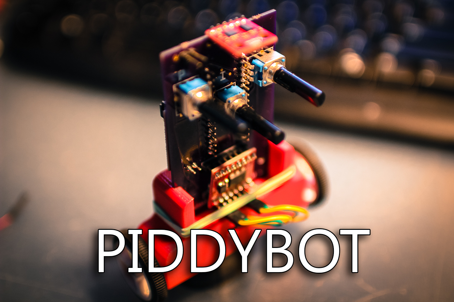
[Sean] created the piddybot, a tiny balancing robot aimed to teach the basics of PID control by trying to get the robot to stand still. More interestingly, the Proportional / Integral / Derivative values can directly be adjusted using the three on-board potentiometers. This will allow users to get the feel of each parameter’s impact on the robot behavior. The piddybot is based around the Arduino nano, a custom PCB, 2x 26:1 geared motors, one 1A dual motor driver board, a six degrees of freedom Inertial Measurement Unit, 2 batteries and finally a 3D printed body. You can check out a video of the robot in action after the break.

This project stems from a non-PID self balancer which [Sean] hacked together in September.

Continue reading “PIDDYBOT – A Self Balancing Teaching Tool”

Making A Variable RF Signal Sampler

One of [Brian]’s hobbies is Amateur Ham radio, in which it is usually required to check that the transmitted signals are within specifications. As it isn’t safe to connect the radio’s output directly to measuring equipment due to the high voltages involved, [Brian] made his own dedicated RF signal sampler. It works by using capacitive coupling between the signal you wish to sample and a high impedance output. The latter can then safely be connected to an oscilloscope or spectrum analyzer for monitoring.

In the picture you see above, the air gap between the core signal conductor and the output plays the role of a capacitor. By adjusting its length you can therefore vary the output signal’s voltage range. The sampler is built using a die-cast aluminium enclosure which is 52x38x27mm. As you may have guessed, due to the case geometry the output attenuation will depend on the signal’s frequency. [Brian] tested the unit using a 30MHz signal generator and printed this frequency attenuation graph while also varying the air gap.

A Simple LED Flashlight Composed Of A Relay And A Magnet

In our tips line we sometimes receive hacks that are amazing just because of their ingenuity. This relay-powered flashlight is definitely one of them. It has been named RattleGen by its creator [Berto], who apparently often makes simple hacks used in his everyday life (have a look at his YouTube channel).

To understand this hack, you first need to know (in case you didn’t already) that a magnet moving near a conductor (here a coil) induces a voltage at its terminals. This is called electromagnetic induction. In the picture you see above, you may distinguish a disassembled relay with a magnet located on the lever’s end. As a ferromagnetic metal is already placed inside the coil, the lever is by default ‘stuck’ in this position. By continuously pressing the latter on its other end, important voltage spikes are created at the coils terminals. [Berto] therefore used a bridge rectifier to transform the AC into DC, and a 1000uF capacitor to smooth the power sent to his super bright LED. A video of the system in action is embedded after the break.

Continue reading “A Simple LED Flashlight Composed Of A Relay And A Magnet”

Developed On Hackaday: We Have Pixels!

It has been a while since we kept you informed about the current state of the Mooltipass project. Well, several days ago we finally received the PCBs we got produced at Seeedstudio. Keep in mind that this first version (shown in the picture above) is only meant to check that the chosen components can suit our needs while our mechanical contributors work on their designs. Moreover, we may add empty footprints for our readers that may want to hack the device.

After a few hours of soldering and a few days of coding, we finally got a basic firmware running. The OLED screen is easily readable and has an amazing contrast (the picture doesn’t do it justice). So far we checked all basic functionalities of the on-board components and it’ll still take a few days/weeks to be certain that we can settle with them. We are therefore starting to ship a few platforms to the firmware developers that want to work on the core functions of the Mooltipass. So if you’re an experienced C developer and have some spare time, you may get onboard by contacting me at mathieu[at]hackaday[dot]com or by joining the Mooltipass Google Group.

In a few days we will publish the designs that our mechanical guys came up with and we’ll ask you to let us know which ones are your favorites. Depending on how things will go, we may produce PCBs for several of them to select our final design based on user experience and ease of use. We look forward to hearing your feedback in the comments section below!

A Simple (and Dirty) Bill Of Materials And Stock Management Utility

As many readers may already know, when I’m not featuring your projects or working on the mooltipass I try to make simple things that may be useful to electronics enthusiasts. My latest creation is a simple bill of materials generation tool, which can also do simple stock management. Unfortunately for Linux users, this utility is made using Visual Basic functions in an Excel file.

It works fairly simply: just enter your schematics’ components references in the excel sheet, along with the corresponding Digikey webpage address. Click on the “fetch” button and the script will automatically get all your component characteristics from the internet and tell you the component costs depending on the number of prototypes you want to make. Then click the “sort BoM” button and your BoM will automatically be sorted by component type and value. Another functionality allows you to check that all the components present in your BoM are also present on the (very simple) Kicad generated one. Finally, using another Excel sheet containing your current stock, the Bill of Materials will let you know if you have enough components for the assembly stage. A video of the tool in action is embedded after the break, and you can download the BoM template here (.XLSM file) and the corresponding stock file there (.XLSM file).

Continue reading “A Simple (and Dirty) Bill Of Materials And Stock Management Utility”

Designing, Simulating And Testing A Simple Radio Duty-Cycling Protocol For Contiki

A few days ago we featured [Marcus]’ Contiki port to the TI Launchpad, Contiki being an open source operating system dedicated to the Internet of Things created by [Adam Dunkels] at the SICS in Sweden. Part of [Marcus]’ work involved designing a simple radio duty-cycling protocol that achieves 3% idle listening duty cycle while allowing for an average 65ms latency with no prior contact or synchronization.

As a few readers may already know, it takes quite a lot of power for a wireless device to listen/send data. A platform therefore needs to have an algorithm that minimizes power consumption while allowing a (regular) planned data transfer. After creating his protocol named SimpleRDC, [Marcus] first simulated it using the Cooja simulator in order to check that it could perform as desired. He then implemented a real life test and checked the protocol’s performance by sniffing the SPI lines connecting his MSP430 to the wireless module and by monitoring the platform power consumption with his oscilloscope and a shunt resistor.

A Tiny Clock With A Retro Display

After having ported Contiki to his TI Launchpad platform, [Marcus] was eager to do something with it. He therefore built a simple clock with a vintage HPDL-1414 “smart four-character 16-segment alphanumeric display” and a msp430g2553.

The result that you can see above is powered over USB, includes a 3.3V LDO linear voltage regulator as well as a button, a LED, a crystal, and several passive components. Fortunately enough, the 5V-powered HPDL-1414 display accepts 3.3V logic at its inputs, avoiding the need for level translators.

The clock program is running on the ported Contiki 2.6 that you can find on his Github repository. [Marcus] is considering using a vibration motor to buzz every 20 minutes during work hours as a reminder for the 20-20-20 rule to battle eye fatigue: every 20 minutes, look at something 20 feet away for 20 seconds. A video of the system in action is embedded after the break.

Continue reading “A Tiny Clock With A Retro Display”