Building An Audio Box Out Of Thrown Away Boards

The last time [Mark] was at the scrap yard, he managed to find the analogue input and output cards of an old Akai DR8 studio hard drive recorder. These cards offered great possibilities (8 ADC inputs, 12 DAC outputs) so he repaired them and made a whole audio system out of them.

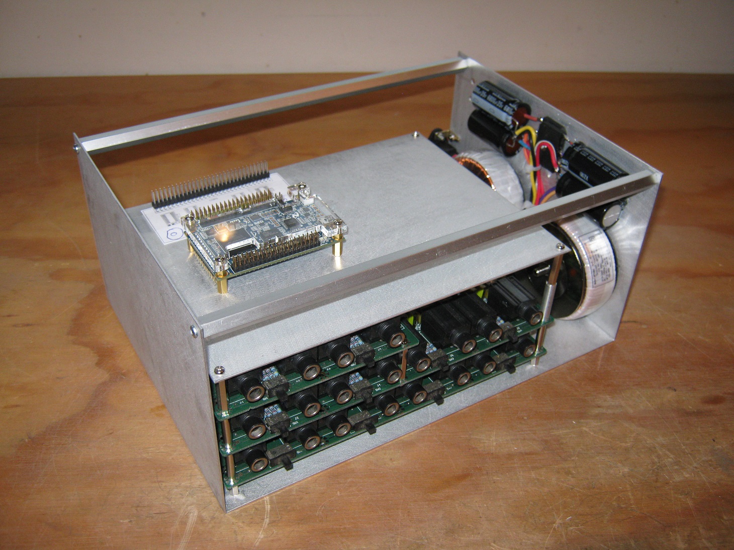
The repair only involved changing a couple of low dropout regulators. Afterwards, [Mark] interfaced one of his CPLD development boards so he could produce some sine waves and digitize signals generated from a PC based audio test unit. He then made the frame shown in the picture above and switched to an Altera Cyclone IV FPGA. To complete his system, he designed a small board to attach a VGA screen,  and another to use the nRF24L01 wireless module.

Inside the FPGA, [Mark] used a NIOS II soft core processor to orchestrate the complete system and display a nice user interface. He even made another system with an USB host plug to connect MIDI enabled peripherals, allowing him to wirelessly control his creation.

Update: Whistled Platform Upgraded For Simple Word Recognition

Some people may remember the whistled platform I [limpkin] designed a while back, which recognizes different whistles to control your lighting. Recently, I designed a firmware that transforms the board into a word recognition device, as the 50MHz ARM Cortex M4’s processing capabilities are good enough to do so.

The simple algorithm works by correlating successive Fast Fourier Transforms (FFT) of the amplified microphone output with the FFTs of a template word previously stored in memory. Simply connect the Whistled to your power supply, say the word you’d like it to recognize and you’re good to go.

As you will see in the video embedded after the break (sorry for the accent…), I briefly explain basic principles about word/sound recognition and what you can do to improve your algorithm performances. The source files can be downloaded, as well as the code for my whistle detection algorithm which wasn’t available the first time we looked at the project.

Continue reading “Update: Whistled Platform Upgraded For Simple Word Recognition”

A Fast And Easy-to-use Vision Sensor

At Hackaday we don’t often feature kickstarter campaigns, but this one is worth noticing in our opinion. It is called Pixy, a small camera board about half the size of a business card that can detect objects that you “train” it to detect.

Training is accomplished by holding the object in front of Pixy’s lens and pressing a button. Pixy then finds objects with similar color signatures using a dedicated dual-core processor that can process images at 50 frames per second. Pixy can report its findings, which include the sizes and locations of all detected objects, through one of several interfaces: UART serial, SPI, I2C, digital or analog I/O.

The platform is open hardware, its firmware is open source and GPL licensed, making the project very interesting. It is based on a 204MHz dual core ARM cortex M4 & M0, uses a 1280×800 image sensor and can stream the processed camera output to your computer. You can get one Pixy in the kickstarter campaign for $59, which is not that expensive for what it is.

Building An Analog Whistle Detection Device

Hackaday readers may remember a whistle detection device that I [limpkin] designed some time ago. As [Kevin] saw the new Staff roll call, he discovered this project and wanted to make his version of it.

In contrast with the original Whistled where all the signal processing is done in an ARM Cortex m4 microcontroler, [Kevin] uses discrete components, operational amplifiers and an Arduino Uno to detect someone’s whistle. In his video (embedded below), he goes into great lengths to explain how his circuit works along with the theory behind it. In his setup, his microphone’s signal is amplified, passed through a 1KHz-3KHz passive band-pass filter to a non-inverting amplifier with a 1000x gain (!) and finally to a voltage comparator. The Arduino measures the frequency of the signal coming out from the comparator and triggers a relay if the whistle is a ramp-up / ramp-down.

If you want to make the comparison between the two versions of the electronics, here is the link to the original whistled project.

Continue reading “Building An Analog Whistle Detection Device”

Update: Testing The Accuracy Of A Magnetic Rotary Encoder

A while back we featured a magnetic rotary encoder that [LongHairedHacker] designed. The heart of the system is an AS5043 magnetic rotary sensor which runs from $6.5-$11 and has a 10 bits precision. As we wanted to check if his design was really efficient, he made a test bench for it.

For 360 degrees, a 10 bits precision means a ±0.175º accuracy, which is quite impossible to check with conventional measurement equipment. The first approach he thought of was to attach a mirror to the encoders axis and point a laser beam at it. The laser beam would be reflected across the room to a big scale, but the minimum required distance would have been 5 meters (16 feet). So he preferred attaching a motor to the sensor, rotating at a given speed and measuring the sensor output.

In the first part of his write-up, [LongHairedHacker] lays the math which explains the different kinds of errors that should be expected from his setup and sensor. He then proceeds with his test, where an ATMEGA8 based board is used to send the measured position to his computer. It should be noted that [LongHairedHacker] currently uses the time spent between two received measurements on his computer as a time base, but he is planning on time stamping the data on his board in the next future. Nevertheless, he managed to measure an average ±0.179º accuracy with his simple test bench, which is very close to the manufacturer specification.

Here is the link to our original post about his sensor.

Reverse-engineering Old Finnish Metro Station Displays

This project definitely was a patience tester. As the control system of the Helsinki metro was (and still is) under big renovation, [Konsta] could buy three old information displays for a very cheap price (5€ each). However, these displays came with no information whatsoever about the way to drive them, thus starting a long reverse-engineering journey.

[Konsta] started by taking one apart, discovering that each side of the display was composed of 10 daisy-chained LCD screens and some kind of control box. As you may have guessed, the key to reverse engineering the display was studying the contents of this box. It turned out that the control electronics were composed of an 8085 CPU, some RAM, a peripheral I/O chip, an UV-erasable EPROM chip (containing 32KB of program memory) and an EEPROM.

[Konsta] used an AVR to dump the memory contents of the two latter chips and it was at this part of the project that the Helsinki Hacklab joined in. Together, they reverse engineered the control PCB, studied the assembler code, sniffed the different on-board buses to fully understand how the display could be controlled.

We strongly recommend reading [Konsta]’s writeup, especially knowing that he made this english page just for us!

Building An Entire Pinball Machine From Just The Playfield

It all started  when [Iancole] bought a Fireball Home edition playfield on some famous auction website for $135. Originally, he had the intent of lighting the lamps with an Arduino, framing it, and hanging it on the wall of his office — which often happens with old pinball parts. But then his boys asked if he “could make it play”.

[Iancole] managed to find the pinball schematics online and started designing the electronics required by the many LEDs, solenoids and switches. As the LEDs and switches are on the same matrix, he chose a simple Arduino to cycle through them, giving the player the impression that the lights are constantly on. [Iancole] originally planned on using his raspberry Pi to control the solenoids, but he later switched to another Arduino because of the precise timing required.

Therefore, his Pi was used as the heart of the machine. It is interfaced to the two Arduinos to read states and send commands while running the game program, displaying HD graphics on a 24″ screen, playing music and game event sounds. All the electronics are proudly displayed on the backbox, and many developments are planned for it. Also, the machine will be on display at the Orlando Mini Maker Faire on October 5th!