Renaming Parts In Eagle CAD By Editing The XML Directly

eagle-xml-find-and-replace-script

There’s a lot of ways to burn up your time when designing PCBs, but renaming components can be one of the most frustrating. [Joe Pinzone] wrote in with his solution to the problem. Instead of hunting for each part on the schematic to change them one at a time, he makes a list of the substitutions and then uses a script to make all the changes in the XML files. He didn’t publish a post about his work, but you’ll find the source code he wrote embedded after the break.

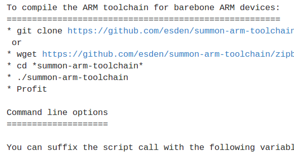
The straw that finally broke the camel’s back was a project that included about two hundred components which didn’t seem to have a naming order that made any sense with the actual values of the components. The script is written in C++ (for Windows but [Joe] says this should be easily ported to other systems as well). To use it he creates a CSV file with the current component names in the first column. He then goes through and types what he wants for the new name in the second column. This CSV, along with the BRD and SCH files are then given as inputs for the script (through selecting them all and dragging to the script or as CLI arguments) and it automatically makes the changes.

Of course this is only possible because Cadsoft transitioned to using XML files in Eagle 6.

Continue reading “Renaming Parts In Eagle CAD By Editing The XML Directly”

RFID Emulator Card Includes A Learning Mode

rfid-emulator

This RFID card has a lot of nice features. But the one that stands out the most is the ability to learn the code from anther RFID tag or card.

You can see that the board includes an etched coil to interact with an RFID reader. This is the sole source of power for the device, letting it pick up enough induced current from the reader to power the PIC 12F683 seen on the upper left of the board. The underside of the PCB hosts just three components: an LED and two switches. One of the switches puts the device in learning mode. Just hold down that button as you move the board into the magnetic field of the reader. While in learning mode a second RFID tag is held up to the reader. It will identify itself and the emulator will capture the code sent during that interaction. This is all shown of in the video after the break. We wonder how hard it would be to make a version that can store several different codes selected by holding down a different button as the emulator is held up to the reader?

If you want to build your own card reader too here’s a project that does it from scratch.

Continue reading “RFID Emulator Card Includes A Learning Mode”

A Guide And Helper Script For ARM Cross Compiling Toolchain On A Mac

mac-arm-toolchain-script

[Mitchell Johnson] wanted to develop for the STM32F4 Discovery board on his Mac. There are a few ready-to-use options when it comes to the ARM toolchains, but he couldn’t find one that satisfied all of his needs. After working out all the kinks he wrote a guide and tweaked a script to install the ARM tools on a Mac.

The problem he had with some of the pre-packaged tool chains is that they didn’t support the hardware floating point functionality of STM’s Cortex-M4 chips. To get around this without doing his own ground-up build (which can be quite a challenge) he forked the Summon Arm Toolchain script and modified it to include ST-Link support in the build. One of the things that we like about that script is it installs the tools in a sub-directory of your home directory. This way if you already have another ARM toolchain you can switch between the two by tweaking your PATH variable.

Humble Beginnings Of A Home Automation Project

humble-beginnings-to-a-home-automation-project

This board is the start of [Steven Pearson’s] quest to automate his home. The module will be used to prototype the rest of the project. Right now it uses an ATmega328 chip running the Arduino bootloader. This connects to one mechanical relay which we would wager is mains rated. The module will be controlled wirelessly via the wireless module seen in the foreground. That is a nRF24L01 board which he chose because of it’s bargain basement price tag of around $1.50.

There is much room for expansion in the system. You can see that a light-dependent resistor has been added to some of the microcontroller’s breakout pins. We would guess that [Steven] will use the hardware to develop for many different functions and will design more task-specific modules as the project progresses.

If you’re a fan of PCB milling and population you won’t want to miss the video after the break. [Steve] posted a fast-motion video of the entire process.

Continue reading “Humble Beginnings Of A Home Automation Project”

TP-Link TL-WR703N Specialized Firmware Generator

Seen at the center of this image is a TP-Link TL-MR3020 which is basically a TL-WR703N wireless router with a few extra LEDs. We’ve seen a lot of projects using this hardware and that’s because it’s cheap and ripe for hacking. The devices can run OpenWRT, a Linux distro for routers that greatly extends the functionality when compared to the stock firmware. Now a couple of members of Shackspace — a hackerspace in Stuttgart, Germany — have written a script that automatically generates specialized firmware for the router. That link goes to their wiki page about the script, but you may find this overview post to be an easier read.

The concept is that gathering specialized hacks into easy to flash packages does away with a lot of configuration headaches. For example, if you just want to play around with an NFC reader for a day-long event you can connect hardware like what is seen above and use the NFC-gate option of the script to flash firmware meant to drive it. So far there’s also support for streaming a USB webcam, serving as a USB network bridge, and a few others. But the whole point of this is to make it simple to roll new firmware mods into the script that make it easy to preserve the work for use at a later time.

[Thanks Hadez]

Hackaday Links: January 17th, 2013

Free-formed VFD clock

links-free-formed-vfd-clock 
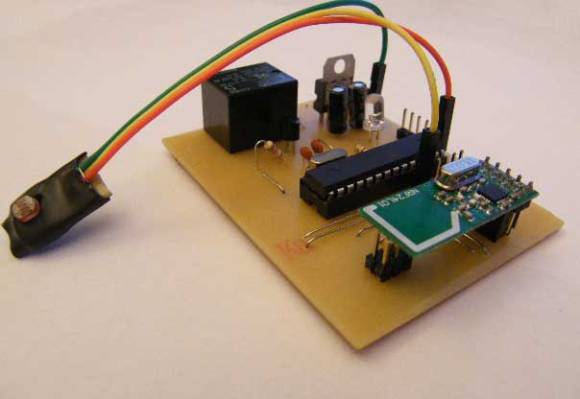
[James] doesn’t need a circuit board or even some protoboard to get the job done. He free-formed all the circuits for his VFD clock. Right now this is the only project hosted on his blog so click around to see how he got to this point.

DIY LED traffic light

links-diy-traffic-light

Here’s a scratch-build traffic light which [Jarle] uses to display information about his server. If you’re unable to find your own storm damaged original this is a pretty easy way to build one.

FPGA space attack game

links-classic-shooter-running-on-fpga

This game is running on an FPGA, but it’s not written in HDL. Instead, [Johan] wrote the game in C to run on a soft processor loaded on the gate array.

Hourglass entropy

links-hour-glass-entropy

This is a fascinating idea for generating random numbers. [Gijs] is shining a laser onto a light dependent transistor. The beam of the laser is broken by the falling sand of an hourglass. This technique could be use as an entropy source for random number generation.

GPS clock source for a digital timepiece

links-gps-clock

It seems like massive overkill, but you can’t beat the time accuracy of using a GPS module as a clock source. We don’t expect that [Jay] kept the clock in one piece after finishing the project. It’s just a good way to practice decoding the GPS data.

Google Talk Bot Running On Raspberry Pi

google-talk-raspberry-pi

[Michael Mitchell] put together a demonstration of how Google Talk can be used to communicate with scripts. Although the concept isn’t new we haven’t seen very many projects that use the chat interface for issuing commands and receiving data. The one that does come to mind is this home automation project which uses Google Talk because it’s quite a bit faster than SMS or email communications.

Luckily there’s already a Python library called pygtalkrobot which helps with the XMPPPY protocol used by Google Talk. In addition to that package, [Michael] also installs some extras which allow him to access the GPIO pins on the RPi via Python. In the video after the break he demonstrates switching and LED on and off, as well as reading from a slide switch connected to pin 8. Of course it’s a snap to code feedback from the OS itself. As you can see in the image above the RPi is reporting it’s uptime after being issued a command by [Michael]

Continue reading “Google Talk Bot Running On Raspberry Pi”