Dabbling With CPLD Generated VGA Signals

It seems like all the cool kids are leaving the 8-bit hobby microcontrollers in the parts bin and playing with more advanced parts like Complex Programmable Logic Devices. [Chris] is no exception to the trend, and set out to generate his own VGA signal using one of the beefy semiconductors.

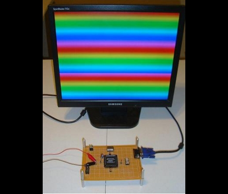
It seems that he’s using the acronyms CPDL and FPGA interchangeable in his post but according to the parts list this setup uses an Altera EPM7128SLC84-7N CPLD. In order to generate the VGA signal he needed a way to convert the digital signals from the chip into the analog values called for in the video standard. He chose to build a Digital Analog Converter for the RGB color values using a resistor network which he calculated using PSpice. The other piece in the puzzle is a 25.175 MHz oscillator to clock the CPLD. As you can see after the break, his wire-wrapped prototype works exactly as designed. The example code generates the rainbow bars seen above, or a bouncing box demo reminiscent of a DVD player screen saver.

Want to know more about programming CPLDs? We did a tutorial on the subject a while back.

Continue reading “Dabbling With CPLD Generated VGA Signals”

Light Painting – Still Shots And Animations

[Kim Pimmel’s] been doing some really interesting light painting with an Arduino. In the past we’ve seen several light painting projects which use long exposures to capture moving LEDs, or moving LCD displays. But [Kim’s] stepping it up a notch, using cold cathode flourescent lamps, electroluminescent (EL) wire, and lasers. The vibrant colors put out by these sources make for some great photos, but that’s not all she’s got up her sleeve. After accumulating a ton of still photographs from various shoots she decided to edit them together into stopped motion videos.

After the break you can see that one method she used to make these images was to spin the light sources on a standard audio turntable. An Arduino is controlled through processing via Bluetooth in order to move the stepper motor-mounted lights while the record player spins. Add some futuristic music thanks to Daft Punk (which is exactly what she did) and you’re in business.

Continue reading “Light Painting – Still Shots And Animations”

Analog Projection Clock So Simple You Should Have Thought Of It

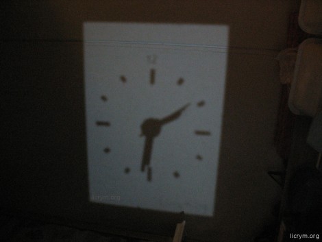
The image you see above is the result of a simple analog projection clock. It shows the time on the ceiling. We have one in our bedroom but it’s a red digital display which we don’t think is nearly as fun as this clever hack. Grab a cheap analog clock, a mirror, and a white LED and you can build your own.

The mirror is going to reflect light from the LED onto a ceiling or other surface. It acts as the clock face. The tick marks for each hour were made by scratching the reflective material (often called the silvering) from the back of the mirror. A hole is drilled at the center of the class and the analog clock is mounted with its hands on the business side. The one problem with this setup is that since the light is being reflected, the clock will appear to run backwards. Not a problem, if you just reverse the polarity of the coil which moves the clockwork the projection will move in the expected clockwise direction.

[via Make]

Cutting Paper Scrolls With Frickin’ Lasers

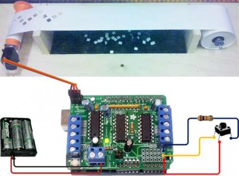
This circuit illustration adds a scrolling paper feeder to the bed of a laser cutter. In the video after the break you can see that the actual assembly is put on the bed of the laser cutter. After the laser has cut out the specified pattern, the scroll is wound to move an un-cut portion into place. It uses a servo motor to drive one of the spools.

An Arduino Uno with a servo shield is being used for this application. It has one button which winds one spool for a pre-programmed period of time. There’s a few issues with this setup, namely that it’s not tied into the CNC program that runs the laser. There’s also a lack of precision when using a continuously rotating servo like this. If it were upgraded to use a stepper motor and patched into the CNC hardware this would make cutting new scrolls for your player piano a breeze.

Here’s a project that does the opposite, it takes old player piano rolls and digitizes them.

Continue reading “Cutting Paper Scrolls With Frickin’ Lasers”

Build Your Own Programmable Logic Controller

[Q] is an Electrical Engineer who works in an industrial setting. He frequently uses Programmable Logic Controllers at work but had never built one himself. He decided to undertake the project at home and managed to build a PLC that outputs 120V AC or 12 V DC and has optoisolated inputs.

On the circuit board you’ll find an ATmega8 and an EEPROM for extra data storage. Six outputs are controlled by relays since they are able to output either alternating or direct current. There are eight inputs which use optical isolators as buffers to protect the microcontroller.

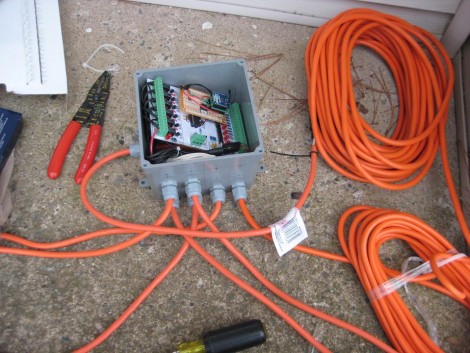
So what did he end up using this for? It was part of his Christmas light setup last year. The image above shows the PLC in a water-tight electrical box with extension cords running to each of the devices he wishes to control. The example code is what he used on the X-mas setup, but it should be enough of a guide to program this to work with just about any application.

Marble Machines Roundup

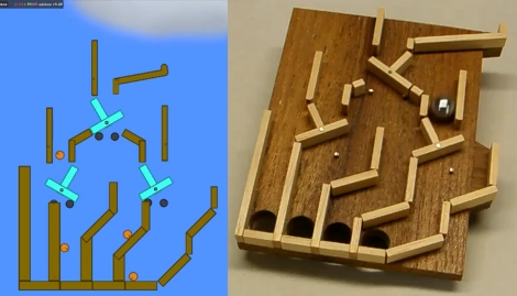
[Denha’s] been building marble machines for years and decided to look a back on some of his favorite marble-based builds  (translated). There’s a slew of them, as well as some thoughts about each. Our favorite part is the digital simulations of the projects. For instance, the image above shows a flip-flop marble machine that was built in a physics simulator. This makes it a lot easier to plan for the physical build as it will tell you exact dimensions before you cut your first piece of material. Both of these images were pulled from videos which can be seen after the break. But this isn’t the most hard-core of pre-build planning. SolidWorks, a CAD suite that is most often used to design 3D models for precision machining, has also been used to model the more intricate machines.

Continue reading “Marble Machines Roundup”

Building Your Own Router Lift-out Mechanism

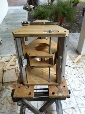
Adjusting the bit height on a router table can be a pain in the butt. Traditionally you needed to get into the cavity under the table top in order to make these adjustments, and it’s hard to make the adjustment and measure the height at the same time. Modern routers now offer the option to adjust height through a hole in the plate that sits in the router table, but this is usually only found on the more expensive models. Rather than buy a new tool [Urant] built his own router lift.

He’s using recycled closet rails to give his rig some smooth operation. These are the rails and runners that let closet doors hang from the top jamb. He saved them when replacing the closet doors in one of his rooms. There’s a triangular gantry which hosts the router, allowing it to move vertically on the three sets of rails. The threaded rod in the foreground of the picture above lets the woodworker adjust bit height by turning the nut at the top. Once mounted in the router table the nut is accessible through a small hole in the table surface.