Keypad Input Scanning By A 555 Timer

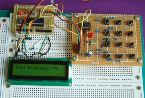
[R-B] designed a 555 timer circuit to scan a keypad. Keypads are common interfaces for small projects and require row and column scanning by a microcontroller. [R-B’s] setup allows you to reduce the number of pins used on the microcontroller to just two. One is an interrupt that is triggered when any of the buttons are pushed, the other reads the frequency from the 555 chip. Each button has its own resistance which alters the frequency of the 555. The microcontroller reads the frequency for 100ms using a timer. The number of timer overflows that occur during that period directly correspond to the button press (five overflows for the numeral 5, zero overflows for the numeral zero).

We usually debounce our button presses for 40 ms, this is more than twice that amount of time but still not a staggering difference. It does make us wonder if you will miss quick button presses? The only really way to know is to try this out yourself. Check out the video after the break and don’t forget to leave a comment with your own experiences in working with the circuit.

Continue reading “Keypad Input Scanning By A 555 Timer”

Cutting Out Your Own Breakout Boards

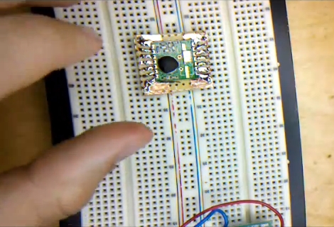
[Caleb] needed to use some surface mount components when prototyping. Instead of buy a breakout board he made one himself without doing any etching. The process he shows off in the video after the break uses copper tape to layout the traces for the board. It’s quite an interesting method which requires a sharp knife and a steady hand.

He used regular protoboard as a substrate and applied a layer of copper tape on the side without copper pads. From there he poked holes for the DIP pin headers. Now it’s time to do some cutting. [Caleb] removed the band of copper that would fall in between the pins of the surface mount device. He then tacked it in place with one dot of solder and drew the traces from the part to the pin headers. After removing the part he cut out the waste in between each line he drew with marker. What he’s left with is a set of thin traces that connect each pin of the surface mount component to the corresponding through-hole pin header.

This is very time-consuming, but then again so is soldering jumper wires to small-pitch components.

Continue reading “Cutting Out Your Own Breakout Boards”

A Different Take On A Laser Projection Microscope

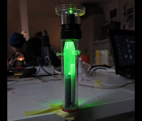
[Dusjagr] has another take on building a laser projection microscope. Last year we saw a laser-based microscope that shined the beam of light through a water droplet which contained the subject to be magnified. The droplet bent the focused beam of light and projected the magnified contents onto a screen. Now that’s pretty neat and [Dusjagr] has used that method himself. But most traditional microscopes use glass slides to contain the subject and this new version now makes that possible.

A bit of experimentation led [Dusjagr] to the discovery that a lens re-purposed from a webcam can achieve similar focus results as a water droplet. The video after the break shows the apparatus seen above in action. The laser shines through the lens, then through a slide that contains a water sample from a nearby pond. The image is clear, albeit completely bathed in green.

For us the most interesting part of [Dusjagr’s] writeup is his discussion of the limits of laser amplification based on the wavelength of light the diode puts out.

Continue reading “A Different Take On A Laser Projection Microscope”

How To Find WiFi: Carry A Big Stick And Use Long Exposures

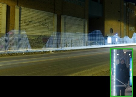
Here’s an artsy way to map out WiFi networks around you; use a big light pole and long exposures to graph them on top of photographs. This capture method is often called light painting, and uses the relative brightness of LEDs to stretch out a still image – moving the stick quickly while the shutter is open.

The four-meter tall rod used in this project plays host to 80 white LEDs. An Arduino along with a WiFi shield detect the relative signal strength of the network surrounding the device. The images that are produced with this method are quite pleasing and you’ll enjoy watching the video after the break. We just wish that there was some kind of Google Street View interface to share this data since someone had to go out pounding the pavement with the rather peculiar looking apparatus in order to gather the data in the first place.

Continue reading “How To Find WiFi: Carry A Big Stick And Use Long Exposures”

This Robot Will School You At Freethrows

People spend years of their lives practicing on the courts to get the kind of accuracy that this robot achieves. It is able to shoot freethrows thanks to stereoscopic camera analysis of the target. We know what you’re thinking; big deal, it knows the distances which makes the calculations easy. That’s not the case, look a bit closer in the image above. The basket itself is mounted on a robotic platform and creates a randomly moving target. It looks like shots are only taken when the basket is stationary. But still, that means the system is able to calculate accurate throws when the basket is not only at varying distances, but also when it is not directly in front and not square to the arm of the robot. The accuracy relies on analyzing the square on the backboard of the basket. Because two cameras give different perspectives, edge and corner detection of both images allow the system to extrapolate the location of the target.

After the fold there’s a video of this robot being demonstrated to the public. Apparently the yellow-armed-monster isn’t suitable for public consumption because the developers have covered it with the body of a plush seal.

Continue reading “This Robot Will School You At Freethrows”

Earthquake Alert System


[Roteno’s] submission for the 555 timer design contest is an Internet connected earthquake alert system. It monitors the USGS website for earthquake data and plays a tune when an earthquake occurs. The data is available as a feed in the form of a TXT file which is pretty easy to parse using cURL. He chose an LPCXpresso board (which is an ARM development platform that can run a Linux kernel) along with an XPORT module to handle the Ethernet traffic.

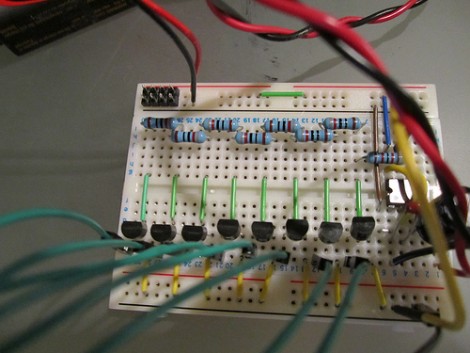
So where does the 555 timer see some action? It is responsible for playing the tone when an earthquake is detected. But playing just one pitch isn’t much fun. Instead, [Roteno] built the circuit above which creates a resistor network switched by a series of transistors. This way he can use GPIO from the microcontroller to choose different pitches. Check out the video after the break to hear the results. At power-up all eight pitches are played as a test, and the alert sound varies in pitch and tempo based on the magnitude of the earthquake.

Continue reading “Earthquake Alert System”

Bluetooth Nixie Driver Lets You Go Almost-wireless

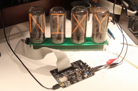
[Bob Coggeshall] has a nice Nixie tube driver board coming down the pipes. It’s not quite ready yet but you can see by the image above, it offers something that isn’t always easy to find; control for B7971 tubes which can display the full spectrum of alpha-numeric characters. This board is not limited to just one type of tube and it can be chained together with other boards to create longer displays. But perhaps the best development is the addition of a Bluetooth module. [Bob] has incorporated a Roving Networks RN-41 Bluetooth module which takes care of all aspects of the wireless protocol. This way the display is not tethered to a computer, or limited to data stored on a chip. We can’t really say that it’s wireless though, as we’d assume a set of these big tubes would rip through batteries pretty quickly. Keep an eye on this project, it will be open source once the bugs are worked out and [Bob] will also sell fully assembled and tested boards for those who choose not to roll their own.

We wonder if it would be easy to pair this with your phone and use it to display incoming call information?