DiY Bike Roller

DIY Bicycle Roller Helps Cure The Winter Blues

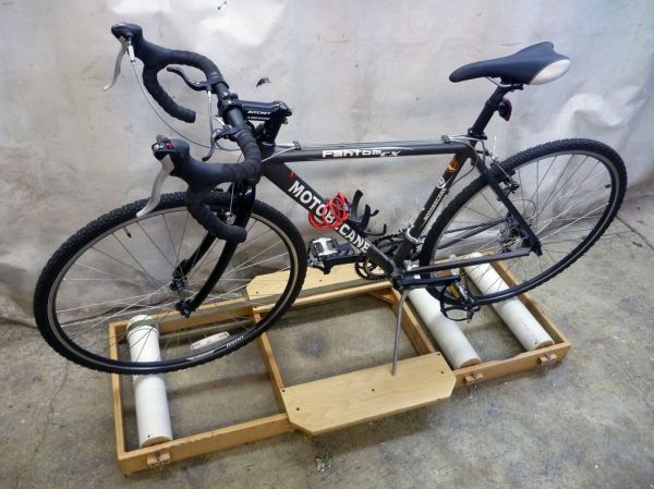
Winter’s a-brewing and that is a downer for the everyday cycling enthusiast. There are certainly ‘bike trainers’ out on the market that will let you ride in your living room but they clamp to (or require replacing the) the rear axle. These bike trainers hold the bike in an upright position so that the rider can’t tip the bike and might feel a little boring for some. There is another indoor biking solution called a bicycle roller which is, just as it sounds, a few rollers on the ground that the bike wheels rest on and is not attached to the bike by any mechanical means. When the rider pedals the bike, the bike wheels spin the rollers. Even with the lack of forward momentum the spinning of the wheels is enough for the rider to stay upright.

[Sky-Monkey] wanted to bike during inclement weather and felt that a bike roller was simple enough for him to try building one. He likes building things and already had all the necessary parts kicking around his shop. The rollers are standard 3″ PVC pipe with plywood discs pressed into each end. The discs are counter-bored to accept standard skate bearings. Off the shelf steel rod make up the axles. The 3 rollers and axle assemblies are mounted in a wood frame made from dimensional lumber. It’s important that the front bike wheel also spins so [Sky-Monkey] made a power transmission belt out of cloth strap that spins the front roller with the rear.

The result is a fully functional bike roller that only cost a few hours of time to make. Video of this puppy in action after the break….

Continue reading “DIY Bicycle Roller Helps Cure The Winter Blues”

Edge Lit Plastic Bike

Edge-Lit Clear Plastic Bike Combines Nighttime Riding Safety With Aurora Borealis Flair

Several years ago [dan] saw some plastic frame bikes designed by MIT students. Ever since he saw those bikes he thought it would be cool to make an edge-lit plastic framed bike.

The frame is made from 1/8″ and 3/8″ thick polycarbonate sheet. The parts were designed with tongue and grooves so they fit together nicely. The joints were glued to hold everything together. Holes were drilled in the edge of the plastic large enough to fit an LED. Once the LED was inserted in the hole, it was wired up and secured with hot glue. There are about 200 LEDs on the bike, powered by a constant current LED driver circuit that [dan] designed specifically for this project.

The build process was certainly not flawless. For example, the plastic holding the bottom bracket (where the crank and pedals attach) broke. This can be avoided by increasing the amount of material in that area prior to cutting out the pieces. [dan] was able to fiberglass his broken parts back together.

[dan] admits that the bike is heavy and a little wobbly, but is definitely ride-able. He did us a favor and made all his CAD files available to anyone that wants to make one themselves. If polycarbonate is too expensive for your blood, check out this bike make from cardboard.

diy video microscope

DIY Video Microscope Used For Soldering SMD Parts

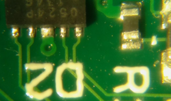
Fortunately (or unfortunately), [ucDude] has had the opportunity to try out a high quality video microscope while soldering some small surface mount components. He loved it, the problem was he had a hard time going back to using just his eyes. He wanted a video microscope but the cost for a professional one could not be justified. The solution? Build one!

[ucDude] called on one of his photographer friends to help. After discussing the project they decided to use a webcam and a lens from an SLR camera. Testing with the webcam resulted in an image that could not be zoomed-in enough, plus having to connect it to an external computer proved to be a bulky solution. They next tried a Raspberry Pi, camera module and zoom monocular. It worked great! The entire assembly was then mounted to a camera boom stand making it easy for the camera to be positioned over the work area and out of the way of hands and soldering irons. The Raspberry Pi’s HDMI output is plugged straight into an HD monitor. The result is exactly what [ucDude] was looking for. Now he can quickly and confidently solder his surface mount circuit boards.


LabVolt Robot Arm Reverse Engineering

Reverse Engineering A Robotic Arm

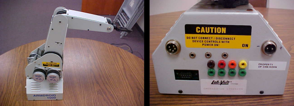
Not too many people will argue that Robot Arms aren’t cool. [Dan] thinks they are cool and purchased a LabVolt Armdroid robotic arm on eBay for a mere $150. Unfortunately, he did not get the power supply or the control unit. To most, this would a serious hurdle to overcome, but not for [Dan]. He opened up the robot and started probing around the circuit board to figure out what was going on.

Since there was a DB9 connector on the outside of the robot arm, he assumed it was a standard RS-232 controlled device. Good thing he checked the internal circuitry because this was not the case at all. There was no mircocontroller or microprocessor found inside.  [Dan] painstakingly reversed engineered the circuit board and documented his results. He found that there were SN76537A chips that drove the 6 unipolar stepper motors and SN75HC259 latches to address each individual motor.

Now knowing how the robot works, [Dan] had to figure out how to control the robot from his computer. He started by making a custom Parallel Port to DB9 cable to connect the computer to the arm. After a series of several programs, starting with simply moving just one arm joint, the latest iteration allows manual control of all joints using the computer keyboard. A big ‘Thanks’ goes out to [Dan] for all his work and documentation.


Chicken_Feed_Indicator

DIY Chicken Feed Indicator Tells You When To Feed The Chickens

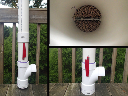
While prepping for the upcoming apocalypse, the [prepforshtf] folks had time to design and build an automatic chicken feeder. It’s a very simple design (the best kind) that is made from standard PVC drain pipe. The pipe is positioned vertically and filled with chicken feed. A T-joint at the bottom of the pipe allows chickens to access the food inside. As food is eaten away, gravity pulls more food down to the feeding area.

That sounds pretty straight forward but it quickly became clear that checking the food level was a chore, almost as much as just feeding the chickens everyday. To remedy the requirement to constantly check the food level, the automatic feeder system was taken apart and modified to include a level indicator. Now, inside the 4-inch pipe resides a plate that resembles a butterfly valve.

This plate doesn’t control the flow of feed like a normal butterfly valve would, the feed actually holds the plate in a vertical position until the feed level drops below the plate. Since the plate has a heavier side, it will rotate when the feed no longer holds it in position. A large red pointer was attached to the plate’s axle and, since it is on the outside of the feeder, it allows a clear indication that the feeder needs a refill.

This is a great project that shows that even simple projects can be very beneficial in everyday life. With no electronics or batteries to fail, this feed indicator will certainly be very reliable. No doubt the chickens will be happy. Check this out for a more involved electricity-powered feeder.

AutoLeveller - PCB Milling Probe

Mill Warped PCB Blanks On An Uneven Bed

Milling a PCB at home is a great way to save some time and money if you are making one-off circuit boards. There is a downside though, it’s a little tough. Sure, just export your Eagle design to CNC-Machine-understandable g-code and fire up your mill…. well, it’s not that easy.

The copper on a PCB blank can be anywhere from about 0.001 to 0.006 inches thick. When milling a board the ideal situation is to mill just deep enough to get through the copper but not cut too deep into the fiberglass backer board. Cutting too deep can weaken the board, break a bit, or in an extreme case, cut through the entire board.

Shallow cuts can result in another problem, inconsistent cut depth over the surface of the board. Check out the left photo above. The traces on the left side of the board appears to have just faded away. This happened because the circuit board was not flat. The side where the traces are missing from is lower than the other so the tool bit is not able to reach that part of the board. Since an ideal depth of cut is about 0.010 inches, even a very small amount of waviness or out of flatness can cause a serious problem in the milling process. If you have a hard time picturing what 0.010 inches is, think the thickness of two pieces of paper, it’s not a lot. There are two main contributors to the flatness problem; the PCB board and/or the machine’s bed. If the bed is not flat, the PCB won’t be. Even if the bed is flat, the PCB may be warped or bent.

PCB fabrication enthusiast [daedelus] had this exact problem, and in true hacker fashion, decided to do something about it. He created a software program called AutoLeveller that takes a g-code file and adds a probing section to the beginning before the milling operation. When the modified g-code file is run on the CNC Machine, it first probes the surface of the PCB in a grid pattern and maps the flatness variation of the PCB’s surface. Then, when running the program, it adjusts the height of the tool bit on the fly so that the actual depth of cut is consistent over the entire board, regardless of how flat or not it is. The result is a clean and usable PCB on the first try.

There is one catch: the Machine Control Software has to be set up to accept a probe. This is easy to do if communicating to the CNC Machine via a computers parallel port. An input pin on the parallel port is pulled high with a resistor and connected electrically to the PCB board. The tool spindle is grounded with a clip lead. When the tool touches the board, the input pin is pulled low and the Machine Control Software records the tool height for that specific XY position.

Continue reading “Mill Warped PCB Blanks On An Uneven Bed”

RaspPi Photo Frame

Raspberry Pi Powered Super Digital Photo Frame

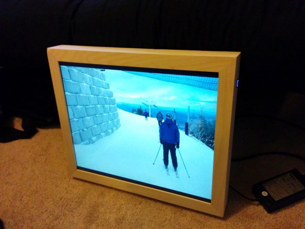
HaD reader [Greg] just finished an LCD picture frame project he’s been working on for a while. This is no ordinary photo display. His brother came up with the idea of having a device to display photos that could be changed remotely. [Greg] gave it some thought and came up with a plan; use a Raspi as the brains, connect to the internet via WiFi and display photos stored in a specific Google Drive folder. Any authorized user can upload photos remotely to the frame so the frame-owner has a constant stream of new photos to view.

Of course, using an off-the-shelf picture frame may have been too easy. Instead [Greg] decided to start with an old computer monitor and wrap it in a wooden frame so it looks good. Mounted to the back of the LCD is a Raspberry Pi with a USB WiFi dongle. The monitor runs at 14 VDC and luckily has an external power supply. Since the Pi runs at 5 V, a buck converter taps into the LCD’s input power and outputs a Pi-happy 5 volts.

This project doesn’t stop with displaying photos! The user can also switch to a weather view. The weather image displayed is generated from weather data pulled from the internet in the exact same manor used by folks who make stand-alone weather displays out of old Kindles. Oh yeah, switching between photos and weather is done by wireless remote! On the frame unit itself there is only one button, but it has 3 functions: A quick press turns the screen off, a short hold syncs with Google Drive and a long hold powers off the RaspPi.

If you’d like to make your own frame, [Greg] has graciously made all his scripts available for download…. not to mention his very detailed build log.