During the 1990s, music was almost invariably stored on CDs or cassette tapes. When the new millennium came around, physical formats became obsolete as music moved first to MP3 files, and later to network streams. But a few years before that big transition, there were several attempts at replacing the aging cassette and CD formats with something more modern. You might remember the likes of MiniDisc and Super Audio CD, but there were a few other contenders around.
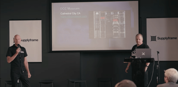
The Digital Compact Cassette, or DCC, was one such format. Released by Philips in 1992 as a replacement for the analog audio cassette, it failed to gain traction in the market and disappeared before most people had even heard of it. Not so for [Jac Goudsmit] and [Ralf Porankiewicz] however, who have spent years researching all aspects of the DCC system and shared some of the results in their 2022 Supercon talk.
[Ralf] is the curator of the DCC Museum in Cathedral City, California, which owns examples of all DCC equipment ever released, as well as several devices that never made it to market. He also aims to document the history of audio recording and DCC’s contribution to it, which goes further than you might think. For example, the audio compression format used in the DCC system, called PASC, was an early version of what would later become MP3 – though most histories of audio compression ignore this fact.
[Jac], for his part, made an extensive study of all the technical features of the DCC format. He has written numerous articles about his findings, first in the DCC FAQ and later by maintaining the relevant Wikipedia articles. He is running several projects aimed at keeping the format alive, often in collaboration with the DCC Museum.
[Jac] and [Ralf] begin their talk with a brief introduction to the system and its media. DCC players were designed to be compatible with analog audio cassettes, so DCC cartridges are the same basic size, though with a different type of tape inside. Playback devices contain a complex set of magnetic heads to read either the analog signals from classic tapes, or the digital data stored on DCCs.
One unique feature of DCC is Interactive Text Transfer Service, or ITTS, which is a separate data area on the tape that can hold additional information like song lyrics or even simple animations. It was intended to be displayed on players that supported it, but no such devices were ever released. Luckily, [Jac] and [Ralf] managed to find a rare ITTS decoder system used in a tape mastering facility, and were able to reveal the contents of this “secret track”, which is present on all prerecorded tapes, for the first time.
User-recorded tapes never had any ITTS data, and differed from prerecorded ones in several other ways, too. The most obvious difference was that professionally-made tapes could be indexed by song title, while home-made ones could only jump to track numbers. [Jac] and [Ralf] are however working to enable all the professional features on home-made tapes as well, through a number of software and hardware projects.
The most basic software needed is an encoder and decoder for the PASC format, which [Jac] developed from existing MP1 sofware. But to explore some of the more obscure hardware features, he had to reverse-engineer several different DCC players. This led him to discover many interesting half-finished features: the ITTS data sector is one example, but he also found out that some players send ready-to-use VU meter data to their front panel, even though they are unable to display that information.
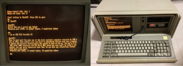
[Jac] was also one of the first people to buy the DCC-175 portable DCC player when it was released in 1995. This was the only DCC player ever sold with a computer interface, allowing direct transfer of digital audio between a computer and a DCC tape. The parallel port interface and its accompanying Windows 9x software are completely obsolete and unusable with modern PCs, so [Jac] is working on directly accessing the data from the DCC-175 through a custom cable. He’s making good progress: he already figured out the electrical interface and wrote some software that enables him to control the tape recorder directly.
We can’t help but be impressed by the amount of effort both [Jac] and [Ralf] have put into understanding and documenting all the intricacies of a long-obsolete audio format. Thanks to their efforts, we can still appreciate the impressive technology behind DCC – even if it never came close to replacing its analog cousin.
Continue reading “2022 Supercon: Jac And Ralf Explore The Secrets Of The Digital Compact Cassette” →
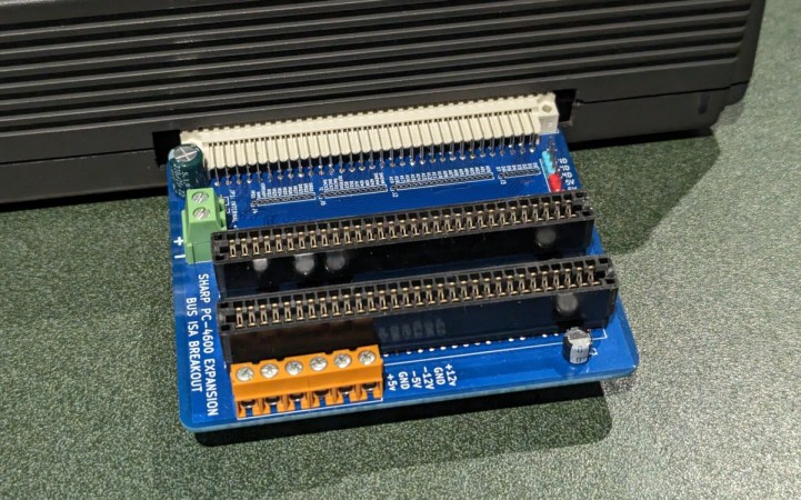
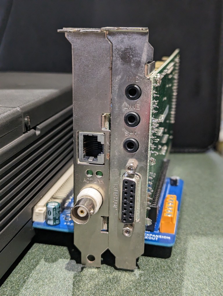 The board also has an external power connector, to avoid overloading the laptop’s internal power supply, as well as a couple of buffer capacitors to smooth out the power rails. [Steven] tested the expansion board with a network adapter and a sound card, and it appears to be functioning well. It should be noted that only the +5 V power rail is available by default, so if any cards need +12 V or any negative rail, those should be provided externally.