Centennial Birthday Of Claude E. Shannon The Math And EE Pioneer

Dr. Claude E. Shannon was born 100 years ago tomorrow. He contributed greatly to the fields of engineering, communications, and computer science but is not a well known figure, even to those in the field. However, his work touches us all many times each day. The network which delivered this article to your computer or smartphone was designed upon important theories developed by Dr. Shannon.

Shannon was born and raised in Michigan. He graduated from the University of Michigan with degrees in Mathematics and Electrical Engineering. He continued his graduate studies at Massachusetts Institute of Technology (MIT) where he obtained his MS and PhD. He worked for Bell Laboratories on fire-control systems and cryptography during World War II and in 1956 he returned to MIT as a professor.

shannon-0Shannon’s first impactful contribution was his masters thesis which took the Boolean Algebra work of George Boole and applied it to switching circuits (then made up of relays). Before his work there was no formal basis for the analysis of switching systems, like telephone networks or elevator control systems. Shannon’s thesis developed the use of symbolic notation to represent networks and applied simplifying rules to optimize the system. These same rules later translated to vacuum tube and transistor logic aiding in the development of today’s computer systems. The thesis — A Symbolic Analysis of Relay and Switching Circuits — was completed in 1937 and subsequently published in 1938 in the Transactions of the American Institute of Electrical Engineers.

Shannon’s doctoral work continued in the same vein of applying mathematics someplace new, this time to genetics. Vannevar Bush, his advisor, commented, “It occurred to me that, just as a special algebra had worked well in his hands on the theory of relays, another special algebra might conceivably handle some of the aspects of Mendelian heredity”. Shannon’s work again is revolutionary, providing a mathematical basis for population genetics. Unfortunately, it was a step further than geneticists of time could take. His work languished, although interest increased over time.

Continue reading “Centennial Birthday Of Claude E. Shannon The Math And EE Pioneer”

Arduino Quadcopter Game Uses Serial Monitor

Every new generation of computers repeats the techniques used by the earlier generations. [Kim Salmi] created an ASCII-based quadcopter simulation game using an Arduino that displays on the Arduino serial monitor. The modern twist is the controller: an accelerometer supplements the joystick for immersive play. And of course there are flashing LEDs.

An Arduino Uno provides the processing power and drives the serial monitor. A joystick and a Hitachi H48C accelerometer are mounted on a breadboard and wired to the Uno. The tilting of the accelerometer controls the height and left-right motion of the quadcopter on the screen. The joystick sets the the ‘copter in hover mode and lowers a ‘rescue’ line. Another LED warns when the maximum height, the vertical limit of the screen, is reached. The joystick also selects one of the three quadcopters, which have different performance characteristics.

There’s a video after the break. [Kim] provides the source code so  you use it as a reference for handling the joystick and accelerometer inputs.

More proof that what is old is new.  Continue reading “Arduino Quadcopter Game Uses Serial Monitor”

Smartphone And IR Line Laser Measure Distance

Measuring the distance using lasers is a mainstay of self-driving vehicles and ambitious robotics projects. The fine folks at MIT’s Computer Science and Artificial Intelligence Laboratory (CSAIL) decided to tackle the problem in an innovative way. [Jason H. Gao] and [Li-Shiuan Peh] used an infra-red (IR) line laser and the camera on a smartphone. Their prototype cost only $49 since they used a smartphone that was on hand. The article reports good results using the device outdoors in direct sunlight which is often a challenge for inexpensive lidars.

The line laser creates a horizontal line that is reflected back to the camera on the phone. The vertical position of the laser on the camera image lets the phone calculate the distance by parallax. To bring out a faint laser reflection, the algorithm compares four images – two with the laser on and two with it off – and subtracts the background. Using a smartphone for this is ideal since it automatically adjusts for light level and can easily be upgraded to a newer phone with a better camera later.

This should be a cheap and easily replicable setup. If you make one of these, let us know. If you need something more refined, check out this post on interfacing the Neato vacuum cleaner’s XV-11a lidar with the Raspberry Pi.

Continue reading “Smartphone And IR Line Laser Measure Distance”

Petite Package Provides Powerful Robot

The Robot Operating System (ROS) is typically associated with big robots but [Grassjelly] decided to prove differently by creating Linorobot. This small, differential drive robot is similar in appearance to many small Arduino based robots often used for line following. Linorobot packs a lot more computing power with a Teensy 3.1 connected to a Radxa Rock Pro. The Teensy handles the motors, reading their encoders, and acquisition of IMU data.

The Radxa, new to us here at Hackaday, is a single board computer based on the quad-core ARM Cortex-A9 1.6 GHz CPU. It may not have been seen on our pages but if you’re at Hackaday Belgrade you can attend a session on building a cluster using it. The ability to run Linux is key to using ROS, which is an open source system for controlling robots. With the Radxa running ROS it interfaces directly to the Neato XV-11 Lidar’s dedicated controller board.

The Linorobot packs into a small robot the capabilities usually seen in much larger and expensive robots such as the Turtlebot 2. With this diminutive robot hackers can learn about doing SLAM (Simultaneous Localization and Mapping) and autonomous navigation, plus the other capabilities of ROS.

[Grassjelly] has a tutorial on building the robot which is also a good introduce to ROS. He provides the software as open source. It’s an impressive project which provides a small, comparatively affordable robot for learning and working with ROS. A video of Linorobot SLAMing and navigating [Grassjelly’s] lab is after the break.

Continue reading “Petite Package Provides Powerful Robot”

Fail Of The Week: Battery Pack Jack Wired Backwards

Last Saturday I had a team of teenage hackers over to build Arduino line-following robots from a kit. Everything went well with the mechanical assembly and putting all the wires on the correct pins. The first test was to check that the motors were moving in the proper direction. I’d written an Arduino program to test this. The first boy’s robot worked fine except for swapping one set of motor leads. That was anticipated because you cannot be totally sure ahead of time which way the motors are going to run.

The motor’s on the second robot didn’t turn at all. As I checked the wiring I smelled the dreaded hot electronics smell but I didn’t see any smoke. I quickly pulled the battery jack from the Arduino and – WOW! – the wires were hot. That didn’t bode well. I checked and the batteries were in the right way. A comparison with another pack showed the wires going into the pack were positioned properly. I plugged in another pack but the motors still didn’t run.

I got my multimeter, checked the voltage on the jack, and it was -5.97 V from center connector to the barrel. The other pack read 6.2 V. I had a spare board and pack so swapped those and the robot worked fine. Clearly the reverse polarity had zapped the motor control ICs. After that everyone had a good time running the robots on a course I’d laid out and went home pleased with their robots.

After they left I used the ohmmeter to check the battery pack and found the wiring was backwards, as you can see in the feature photo. A close inspection showed the wire with a white line, typically indicating positive, indeed went to the positive battery terminal. I shaved the barrel connector down to the wires and the white line wire was connected to the outside of the barrel. FAIL!

This is a particularly bad fail on the part of the battery pack supplier because how hard is it to mess up two wires? You can’t really fault the robot kit vendor because who would expect a battery pack to be bad? The vendor is sending me a new battery pack and board so I’m satisfied. Why did I have an extra board and pack, actually an entire kit? For this exact reason; something was bound to go wrong. Although what I had imagined was for one of the students to break a mechanical part or change wiring and zap something. Instead, we were faced with a self-destructing kit. Prudence paid off.

Teensy 3.1 Controlled VFO

[Tom Hall], along with many hams around the world, have been hacking the Silicon Labs Si5351 to create VFOs (variable frequency oscillators) to control receivers and transmitters. You can see the results of his work in a video after the break.

vfo board
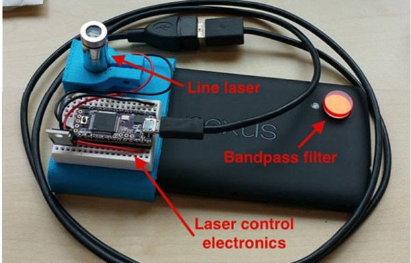
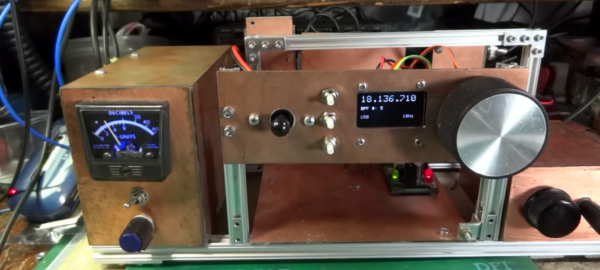
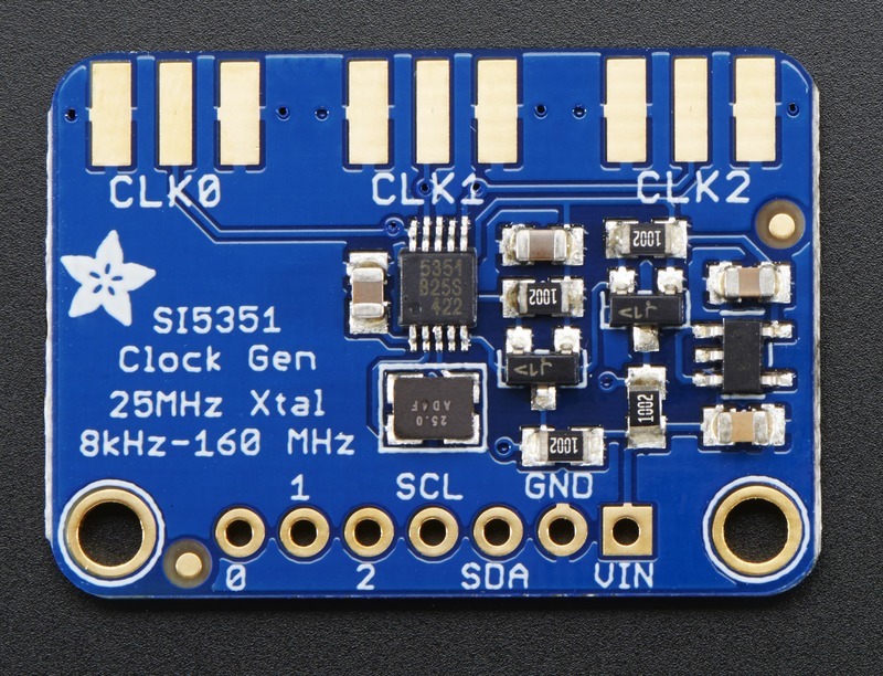
[Tom] used a Teensy 3.1 Arduino compatible board, to control the Si5351 mounted on an Adafruit breakout board. An LCD display shows the current frequency and provides a simple interface display for changing the output. A dial encoder allows for direct adjustment of the frequency. The ham frequency band and the frequency increment for each encoder step are controlled by a joystick. When you get into the 10 meter band you definitely want to be able to jump by kHz increments, at least, since the band ranges from 28 MHz to 29.7 MHz.

So what is the Si5351? The data sheet calls it an I2C-Programmable Any-Frequency CMOS Clock Generator + VCXO. Phew! Let’s break that down a bit. The chip can be controlled from a microprocessor over an I2C bus. The purpose of the chip is to generate clock outputs from 8 kHz to 160 MHz. Not quite any frequency but a pretty good range. The VCXO means voltage controlled crystal oscillator. The crystal is 25 MHz and provides a very stable frequency source for the chip. In addition, the Si5351 will generate three separate clock outputs.

[Tom] walks through the code for his VFO and provides it via GitHub. An interesting project with a lot of the details explained for someone who wants to do their own hacks. His work is based on work done by others that we’ve published before, which is what hacking is all about.

Continue reading “Teensy 3.1 Controlled VFO”

Error Detection And Correction: Reed-Solomon, Convolution And Trellis Diagrams

Transferring data without error when there is a lot of background noise is a challenge. Dr. Claude E. Shannon in 1948 provided guidance with his theory addressing the capacity of a communications channel in the presence of noise. His work quickly spread beyond communications into other fields. Even other aspects of computer use were impacted. An example is the transfer of data from a storage medium, like a hard drive or CD-ROM. These media and their sensors are not 100% reliable so errors occur. Just as Shannon’s work defines communication channel capacity it defines the transfer rate from a media surface to the read head.

Shannon told us how much could be passed through a channel but didn’t say how. Since 1948 a lot of research effort went into accurately detecting errors and correcting them. Error correction codes (ECC) add extra bits to messages, but their cost pays off in their ability to work around errors. For instance, without ECC the two Voyager spacecraft, now leaving our solar system, would be unable to phone home with the information they’ve gathered because noise would overwhelm their signals. Typically in hardware, like memory, error correction is referred to as ECC. In communications, the term forward error correction (FEC) is used.

Robust communication, or data transfer, is a combination of fancy software and tricky signal processing. I’m going to focus on the software side in this article. You may find some of these techniques useful in communicating data among your devices. While I’ll be using the term communications keep in mind this is applicable to transferring data in general.

Continue reading “Error Detection And Correction: Reed-Solomon, Convolution And Trellis Diagrams”