We don’t need to tell you that these last couple of years have been a real drag for in-person events. But at long last, after a bit of a false start last summer, it seems like we can finally start peeking our heads out and getting back to doing the things we love. So why not celebrate by taking part in that most sacred of geek pastimes: poring through boxes of dusty old gear in search of some electronic treasure?
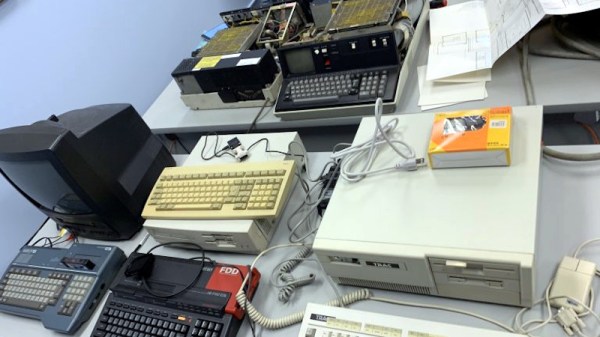
On Saturday the Vintage Computer Federation (VCF) is holding an indoor swap meet at the InfoAge Science and History Museum in New Jersey, and everyone’s invited. Vintage computers will naturally be the main attraction, but if their previous events are any indication, you should expect the tables to be filled with a healthy mix of general electronics, classic games, and amateur radio gear as well. The doors open up at 8 AM sharp and it’s free to get in, so we’d suggest showing up early for the best selection.
A little less than a year ago we visited the previous VCF swap meet, which back then had to be held outdoors due to COVID-19 concerns, and were blown away by the selection of weird and wonderful hardware up for grabs. From arcade cabinets to luggable PCs and 3D printers, there was a little something for everyone, and all at rock-bottom prices. The only real gripe we had was the lack of on-site food and beverage, which according to the VCF website, has been addressed this time around. No word on whether or not there’s an ATM handy though, so you might want to stop and get some cash before heading to the relatively remote Camp Evans site.
The fine folks of the VCF are also hard at work putting together their annual East Coast Vintage Computer Festival, which will take place at InfoAge on April 22nd to the 24th, so mark your calendars.
We’ve all heard it said, and it bears repeating: getting to space is hard. But it actually gets even harder the smaller your booster is. That’s because the structure, engines, avionics, and useful payload of a rocket only make up a tiny portion of its liftoff mass, while the rest is dedicated to the propellant it must expend to reach orbital velocity. That’s why a Falcon 9 tipping the scales at 549,054 kilograms (1,207,920 pounds) can only loft a payload of 22,800 kg (50,265 lb) — roughly 4% of its takeoff weight.
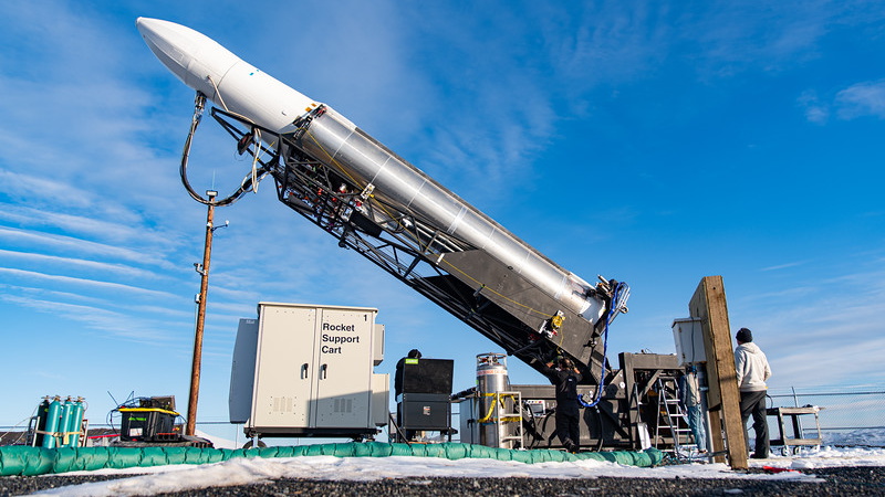
As you might imagine, there’s a lower limit where there simply isn’t enough mass in the equation for the hardware necessary to build a fully functional rocket. But where is that limit? That’s precisely what aerospace newcomer Astra is trying to find out. Their Rocket 3 is among the smallest orbital boosters to ever fly, closer in size and mass to the German V2 of World War II than the towering vehicles being built by SpaceX or Blue Origin. Even the Rocket Lab Electron, itself an exceptionally svelte rocket, is considerably larger.
The reason they’re trying to build such a small rocket is of course very simple: smaller means cheaper. Assuming you’ve got a payload light and compact enough to fit on their launcher, Astra says they can put it into orbit for roughly $2.5 million USD; less than half the cost of a dedicated flight aboard Rocket Lab’s Electron, and competitive with SpaceX’s “rideshare” program. Such a low ticket price would have been unfathomable a decade ago, and promises to shake up an already highly competitive commercial launch market. But naturally, Astra has to get the thing flying reliably before we can celebrate this new spaceflight milestone.
Their latest mission ended in a total loss of the vehicle and payload when the upper stage tumbled out of control roughly three minutes after an otherwise perfect liftoff from Cape Canaveral Space Force Station in Florida. Such issues aren’t uncommon for a new orbital booster, and few rockets in history have entered regular service without a lost payload or two on the books. But this failure, broadcast live over the Internet, was something quite unusual: because of the unconventional design of Astra’s diminutive rocket, the upper stage appeared to get stuck inside the booster after the payload fairing failed to open fully.
One look at the default Winamp skin is sure to reawaken fond memories for a certain segment of the community. For those who experienced the MP3 revolution first hand, few audio players stick out in the mind like Winamp and its llama whipping reputation. No, the proprietary Windows-only media player isn’t the sort of thing you’d catch us recommending these days; but it was the 1990s, and things were very different.
For those who want to relive those heady peer-to-peer days, [Tim C] has posted a tutorial on how to turn Adafruit’s PyPortal into a touch screen MP3 player that faithfully recreates the classic Winamp look. As you can see in the video below it certainly nails the visuals, down to the slightly jerky scrolling of the green track info which we’re only now realizing was probably the developer’s attempt to mimic some kind of a physical display like a VFD.
With minimal UI functionality, playlists must be created manually.
[Tim] has even included support for original Winamp themes, although as you might expect, some hoop-jumping is required. In this case, it’s a Python script that you have to run against an image of the original skin pulled from the Winamp Skin Museum. From there, you just need to edit a couple of lines of code to point the player at the right skin files. In other words, switching between skins is kind of a hassle, but you should at least be able to get your favorite flavor from back in the day up and running.
But before you get too excited, there’s a bit of a catch. For one thing, the Winamp UI isn’t actually functional. You can tap the top section of the screen to pause the playback, and tapping down in the lower playlist area lets you change songs, but all the individual buttons and that iconic visual equalizer are just for show. Managing your playlists also requires you to manually edit a JSON file, which even in the 1990s we would have thought was pretty wack, to use the parlance of the times.
Of course, things could easily be streamlined a bit with further revisions to the code, and since [Tim] has released it into the public domain under the Unlicense, anyone can help out. As it stands, it’s still a very slick media display that we certainly wouldn’t mind having on our desk.
The microphone is a pretty ubiquitous piece of technology that we’re all familiar with, but what if you’re not looking to record audio in the air, and instead want to listen in on what’s happening underwater? That’s a job for a hydrophone! Unfortunately, hydrophones aren’t exactly the kind of thing you’re likely to find at the big-box electronics store. Luckily for us, [Jules Ryckebusch] picked up a few tricks in his 20-year career as a Navy submariner, and has documented his process for building a sensitive hydrophone without needing a military budget.
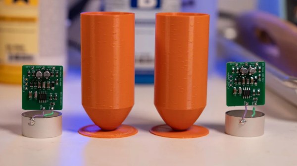
Fascinated by all the incredible sounds he used to hear hanging around the Sonar Shack, [Jules] pored over documents related to hydrophone design from the Navy and the National Oceanic and Atmospheric Administration (NOAA) until he distilled it all down to a surprisingly straightforward build. The key to the whole build is a commercially available cylindrical piezoelectric transducer designed for underwater communication that, incredibly, costs less than $20 USD a pop.
The transducer is connected to an op-amp board of his own design, which has been adapted from his previous work with condenser microphones. [Jules] designed the 29 x 26 mm board to fit neatly within the diameter of the transducer itself. The entire mic and preamp assembly can be cast inside a cylinder of resin. Specifically, he’s found an affordable two-part resin from Smooth-On that has nearly the same specific gravity as seawater. This allows him to encapsulate all the electronics in a way that’s both impervious to water and almost acoustically transparent. A couple of 3D-printed molds later, the hydrophone was ready to cast.
Interestingly, this isn’t the first homebrew hydrophone we’ve seen. But compared to that earlier entry, which basically just waterproofed a standard microphone pickup, we think this more thoughtful approach is likely to have far better performance.
Among the many facets of modern technology, few have evolved faster or more radically than the computer. In less than a century its very nature has changed significantly: today’s smartphones easily outperform desktop computers of the past, machines which themselves were thousands of times more powerful than the room-sized behemoths that ushered in the age of digital computing. The technology has developed so rapidly that an individual who’s now making their living developing iPhone applications could very well have started their career working with stacks of punch cards.
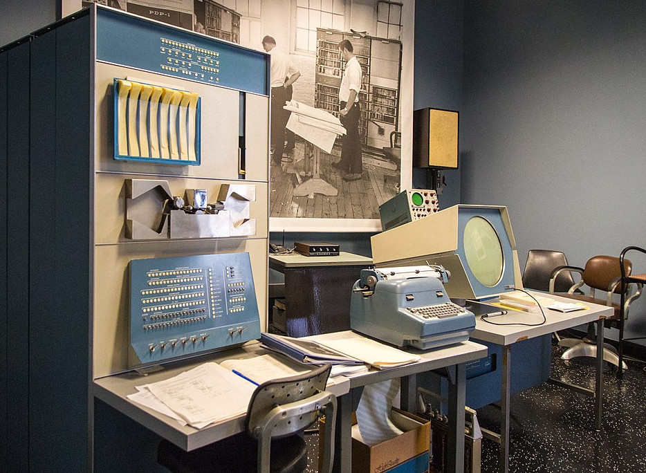
With things moving so quickly, it can be difficult to determine what’s worth holding onto from a historical perspective. Will last year’s Chromebook one day be a museum piece? What about those old Lotus 1-2-3 floppies you’ve got in the garage? Deciding what artifacts are worth preserving in such a fast moving field is just one of the challenges faced by Dag Spicer, the Senior Curator at the Computer History Museum (CHM) in Mountain View, California. Dag stopped by the Hack Chat back in June of 2019 to talk about the role of the CHM and other institutions like it in storing and protecting computing history for future generations.
To answer that most pressing question, what’s worth saving from the landfill, Dag says the CHM often follows what they call the “Ten Year Rule” before making a decision. That is to say, at least a decade should have gone by before a decision can be made about a particular artifact. They reason that’s long enough for hindsight to determine if the piece in question made a lasting impression on the computing world or not. Note that such impression doesn’t always have to be positive; pieces that the CHM deem “Interesting Failures” also find their way into the collection, as well as hardware which became important due to patent litigation.
Of course, there are times when this rule is sidestepped. Dag points to the release of the iPod and iPhone as a prime example. It was clear that one way or another Apple’s bold gambit was going to get recorded in the annals of computing history, so these gadgets were fast-tracked into the collection. Looking back on this decision in 2022, it’s clear they made the right call. When asked in the Chat if Dag had any thoughts on contemporary hardware that could have similar impact on the computing world, he pointed to Artificial Intelligence accelerators like Google’s Tensor Processing Unit.
In addition to the hardware itself, the CHM also maintains a collection of ephemera that serves to capture some of the institutional memory of the era. Notebooks from the R&D labs of Fairchild Semiconductor, or handwritten documents from Intel luminary Andrew Grove bring a human touch to a collection of big iron and beige boxes. These primary sources are especially valuable for those looking to research early semiconductor or computer development, a task that several in the Chat said staff from the Computer History Museum had personally assisted them with.
Towards the end of the Chat, a user asks why organizations like the CHM go through the considerable expense of keeping all these relics in climate controlled storage when we have the ability to photograph them in high definition, produce schematics of their internals, and emulate their functionality on far more capable systems. While Dag admits that emulation is probably the way to go if you’re only worried about the software side of things, he believes that images and diagrams simply aren’t enough to capture the true essence of these machines.
Quoting the the words of early Digital Equipment Corporation engineer Gordon Bell, Dag says these computers are “beautiful sculptures” that “reflect the times of their creation” in a way that can’t easily be replicated. They represent not just the technological state-of-the-art but also the cultural milieu in which they were developed, with each and every design decision taking into account a wide array of variables ranging from contemporary aesthetics to material availability.
While 3D scans of a computer’s case and digital facsimiles of its internal components can serve to preserve some element of the engineering that went into these computers, they will never be able to capture the experience of seeing the real thing sitting in front of you. Any school child can tell you what the Mona Lisa looks like, but that doesn’t stop millions of people from waiting in line each year to see it at the Louvre.
The Hack Chat is a weekly online chat session hosted by leading experts from all corners of the hardware hacking universe. It’s a great way for hackers connect in a fun and informal way, but if you can’t make it live, these overview posts as well as the transcripts posted to Hackaday.io make sure you don’t miss out.
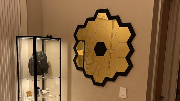
The James Webb Space Telescope (JWST) has become something of a celebrity here on Earth, and rightfully so. After decades of development, the $10 billion deep space observatory promises to peel back the mysteries of the universe in a way that simply hasn’t been possible until now. Plus, let’s be honest, the thing just looks ridiculously cool.
So is it really such a surprise that folks would want a piece of this marvel hanging up in their wall? No, it’s not the real thing, but this rendition of the JWST’s primary mirror created by [James Kiefer] and [Ryan Kramer] certainly gets the point across.
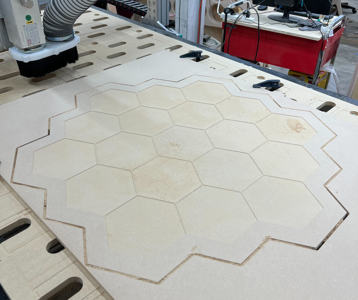
A CNC router was used to cut the outside shape from a piece of 1/2 inch MDF, as well as put 1 mm deep pockets in the face to accept the hexagonal golden acrylic mirrors. We originally thought the mirrors were also custom made, but somewhat surprisingly, gold-tinted hex mirrors are apparently popular enough in the home decor scene that they’re readily available online for cheap. A quick check with everyone’s favorite a large online bookseller turned global superpower shows them selling for as little as $0.50 a piece.
With a coat of black paint on the MDF, the finished piece really does look the part. We imagine it’s fairly heavy though, and wonder how it would have worked out if the back panel was cut from a piece of thick foam board instead.
Of course this isn’t a terribly difficult design to recreate if you had to, but we still appreciate that the duo has decided to release both the Fusion 360 project file and the exported STL to the public. It seems only right that this symbol for science and discovery should be made available to as many people as possible.
After a dramatic launch on Christmas Day and a perilous flight through deep space, the JWST has performed impeccably. Even though we’re still a several months away from finally seeing what this high-tech telescope is capable of, it’s already managed to ignite the imaginations of people all over the globe.
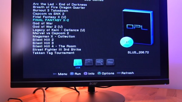
It used to be that to play a console game, you just had to plug in a cartridge or put a CD/DVD in the optical drive. But these days, with modern titles ballooning up to as much as 100 GB, you’ve got no choice but to store them on the system’s internal hard disk drive. While that can lead to some uncomfortable data management decisions, at least it means you don’t have to get up off the couch to switch games anymore.
Which is precisely why the MC2SIO project for the PlayStation 2 is so exciting. As [Tito] explains in his latest Macho Nacho Productions video, this simple adapter lets you connect an SD card up to the console’s Memory Card slots and use that to hold ISOs of your favorite games. With the appropriate homebrew software loaded up, your PS2 becomes a veritable jukebox of classic games.