Recreating One Of History’s Best Known Spy Gadgets

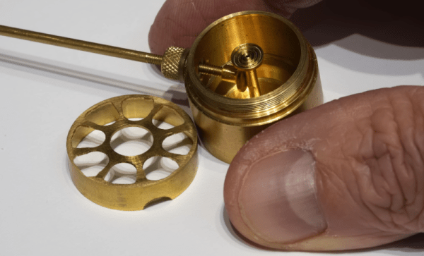
[Machining and Microwaves] got an interesting request. The BBC asked him to duplicate the Great Seal Bug — the device the Russians used to listen covertly to the US ambassador for seven years in 1945. Turns out they’re filming a documentary on the legendary surveillance device and wanted to demonstrate how it worked.

The strange thing about the bug is that it wasn’t directly powered. It was actually a resonant cavity that only worked when it was irradiated with an external RF energy. Most of the video is background about the bug, with quite a few details revealed. We particularly liked the story of using a software defined radio (SDR) to actually make the bug work.

As you might expect, things didn’t go smoothly. Did they ever get results on camera? Watch the video, and you can find out. This is just the first of six videos he plans to make on the topic, and we can’t wait for future videos that cover the machining and more technical details.

We’ve examined the Theremin bug before. There’s a definite cat-and-mouse dynamic between creating bugging devices and detecting them.

Continue reading “Recreating One Of History’s Best Known Spy Gadgets” →
Inside Digital Image Chips

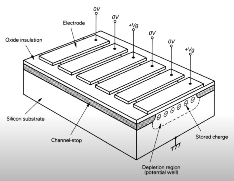
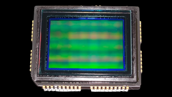
Have you ever thought how amazing it is that every bit of DRAM in your computer requires a teeny tiny capacitor? A 16 GB DRAM has 128 billion little capacitors, one for each bit. However, that’s not the only densely-packed IC you probably use daily. The other one is the image sensor in your camera, which is probably in your phone. The ICs have a tremendous number of tiny silicon photosensors, and [Asianometry] explains how they work in the video you can see below.

The story starts way back in the 1800s when Hertz noticed that light could knock electrons out of their normal orbits. He couldn’t explain exactly what was happening, especially since the light intensity didn’t correlate to the energy of the electrons, only the number of them. It took Einstein to figure out what was going on, and early devices that used the principle were photomultiplier tubes, which are extremely sensitive. However, they were bulky, and an array of even dozens of them would be gigantic.

Semiconductor devices use silicon. Bell Labs was working on bubble memory, which was a way of creating memory that was never very popular. However, as a byproduct, the researchers realized that moving charges around for memory could also move around charges from photosensitive diodes. The key idea was that it was harder to connect many photodiodes than it was to create the photodiodes. Using the charge-coupled device or CCD method, the chip could manipulate the charges to reduce the number of connections to the chip.

CCDs opened up the digital image market, but it has some problems. The next stage was CMOS chips. They’d been around for a while since IBM produced the scanistor, but the sensitivity of these CMOS image chips was poor. Since most people were happy with CCD, there wasn’t as much research on CMOS. However, CMOS sensors would eventually become more capable, and the video explains how it works.

We’ve looked at image sensors before, too. The way you read them can make a big difference in your images.

Continue reading “Inside Digital Image Chips” →

The Keychain 6809

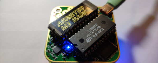
When you think of tiny microcontroller boards, you probably think of a modern surface mount processor. Not [Andreas Jakob]. His 5×5 cm keychain computer rocks a 6809 CPU at a blistering 1 MHz or, if you prefer, a 6309 that runs at 5 MHz. The RAM — all 32K — is in a SMD package to make it fit, but the board also sports a 27C256 EPROM which means that chip and the CPU take up most of the PCB.

As you might expect, there’s not much else on the board. It doesn’t hurt, too, that the PCB is a 6-layer board. The board features a USB C port for power and data, but we didn’t see the USB interface chip on the schematic until we opened it in Easy EDA using the button that says “open in editor.” The schematic says it is sheet 1 or 1, but there are actually two additional “tabs” you can only see in the editor with the apparently missing pieces.

Continue reading “The Keychain 6809” →

Vintage Tektronix Virtual Graticule

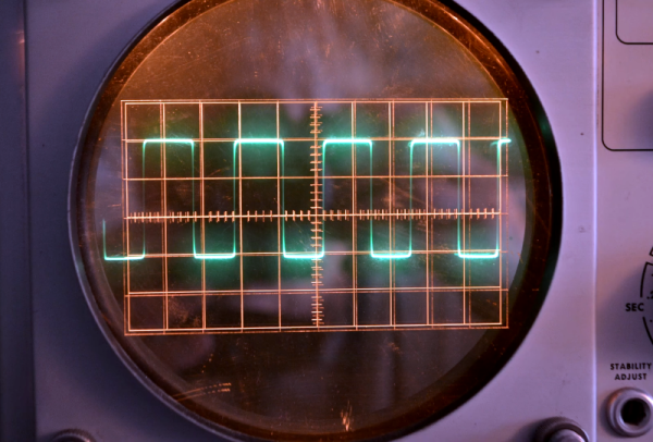
Oscilloscopes are great for measuring the time and voltage information of a signal. Some old scopes don’t have much in the way of markings on the CRT, although eventually, we started seeing scales that allowed you to count squares easily. Early scopes had marks on the glass or plastic over the CRT, but as [Vintage TEK Museum] points out, this meant for best accuracy, you had to look directly at the CRT. If you were at an angle horizontally or vertically, the position of the trace would appear to move concerning the lines on the screen. You can see the effect in the video below.

The simple solution was to mark directly into the phosphor, which minimized the effect. Before that was possible, [Bob Anderson] invented a clever solution, although Tektronix didn’t produce any scopes using it for some reason. The idea was the virtual oscilloscope graticule, and it was quite clever.

The idea was to put the graticule on a semi-reflective mirror. Looking through the assembly, you would actually see the trace and the reflection of the graticule in the mirror. The resulting image is perfectly aligned if the assembly is constructed properly. You can, at some angles, see both the front and reflected graticules.

According to the video, management was not impressed because someone other than [Anderson] showed a poor-quality prototype to them. By 1962, the graticule in the phosphor took over, and there was no need for [Anderson’s] clever invention.

These days, a graticule is just bits on the screen. Even if you roll your own.

Continue reading “Vintage Tektronix Virtual Graticule” →

BitTorrent For Language Models

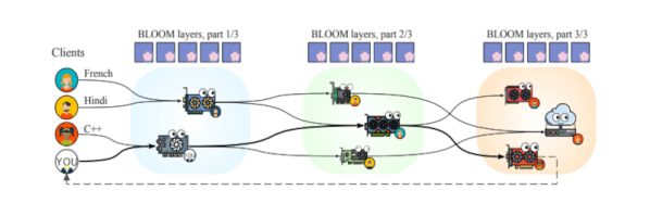
In the old days of the Internet, FTP was sufficient for downloading the occasional file. But with the widespread use of computer audio and video, it was easy to swamp an FTP server so — eventually — BitTorrent was born. The idea was you would download bits and pieces of a file from different places and, in theory, people would download bits and pieces that you have if they need them. Now Petals wants to use this same method with language models. These AI language models are all the rage, but they take significant computer resources. The idea behind Petals is like BitTorrent. You handle a small part of the model (about 8 gigabytes which is small compared to the 352 gigabytes required), and other people have other parts.

Of course, if you are privacy-minded, that means that some amount of your data is going out to the public, but for your latest chatbot experiments, that might not be a big problem. You can install Petals in an Anaconda environment or run a Docker image if you don’t want to set up anything. If you just want to access the distributed network’s chatbot based on BLOOMZ-176B, you can do that online.

Continue reading “BitTorrent For Language Models” →

Cold War Listening Post Antennas

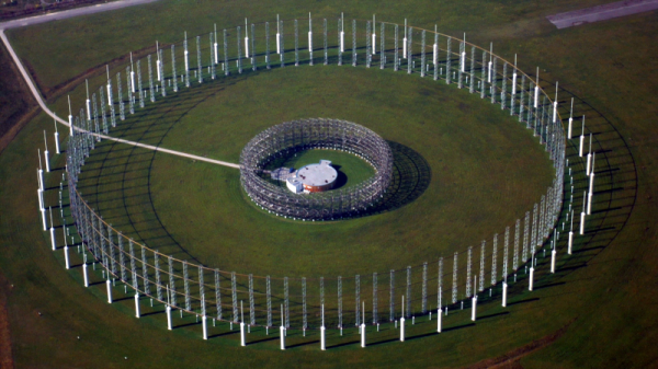
With a UHF antenna, it is easy to rotate a directional antenna to find the bearing to a transmitter. But at HF, it is more common to use an array of antennas that you can electrically switch as well as analyze the phase information between the elements. [Ringway Manchester] has a look at the “elephant cage” antenna used by the US Iron Horse listening network from the 1950s. You can see a video about the giant antenna system, the AN/FLR-9.

Technically, the ring of concentric antenna elements forms a Wullenweber antenna. The whole thing consists of three rings built on a ground screen nearly 1,500 feet across. The outer ring covers from 1.5 to 6 MHz or band A. The band B ring in the center covers 6 to 18 MHz. The inner ring covers band C which was from 18 to 30 MHz.  Band A was made up of 48 monopoles while band B used 96 elements. The much smaller band C elements were 48 pairs of horizontally polarized dipoles. Continue reading “Cold War Listening Post Antennas” →

Advanced 3D Printing Tips

One of the best things about hanging around with other hackers is you hear about the little tricks they use for things like 3D printing. But with the Internet, you can overhear tips from people you’ll probably never meet, like [3D Printer Academy]. His recent video has a little bit of a click-bait title (“10 Secret 3D Printing Tricks…“) but when we watched it, we did see several cool ideas. Of course, you probably know at least some of the ten tips, but it is still interesting to see what he’s been up to, which you can do in the video below.

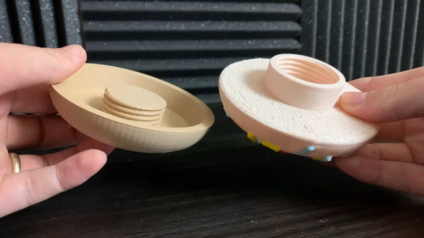
At one point he mentions 11 tips, but the title has 10 and we had to stretch to get to that number since some of them have some overlap. For example, several involve making printed threads. However, he also shows some C-clips, a trick to add walls for strength, and printing spur gears. Of course, some of these, like the gears, require specific tools, but many of them are agnostic.

Some of the tips are about selecting a particular infill pattern, which you’d think would be pretty obvious, but then again, your idea of what’s novel and what’s old hat might be different than ours. The explanation of how a print-in-place hinge works is pretty clear (even if it isn’t really a live hinge) and also applies to making chains to transfer power. We also thought the threaded containers were clever.

So if you can overlook the title and you don’t mind seeing a few tips you probably already know, you can probably take something away from the video. What’s your favorite “expert” trick? Let us know in the comments.

A lot of what we print tends to be enclosures and there are some good tips for those floating around. Of course, the value of tips vary based on your experience level. But if you are just starting out, you should check out [Bald Engineer]’s video of things he wished someone had told him when he started 3D printing.

Continue reading “Advanced 3D Printing Tips” →