By the turn of the 19th century, most scientists were convinced that the natural world was composed of atoms. [Einstein’s] 1905 paper on Brownian motion, which links the behavior of tiny particles suspended in a liquid to the movement of atoms put the nail in the coffin of the anti-atom crowd. No one could actually see atoms, however. The typical size of a single atom ranges from 30 to 300 picometers. With the wavelength of visible light coming in at a whopping 400 – 700 nanometers, it is simply not possible to “see” an atom. Not possible with visible light, that is. It was the summer of 1982 when Gerd Binnig and Heinrich Rohrer, two researchers at IBM’s Zurich Research Laboratory, show to the world the first ever visual image of an atomic structure. They would be awarded the Nobel prize in physics for their invention in 1986.
The Scanning Tunneling Microscope
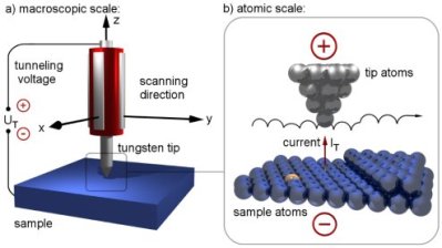
IBM’s Scanning Tunneling Microscope, or STM for short, uses an atomically sharp needle that passes over the surface of an (electrically conductive) object – the distance between the tip and object being just a few hundred picometers, or the diameter of a large atom.
[Image Source]A small voltage is applied between the needle and the object. Electrons ‘move’ from the object to the needle tip. The needle scans the object, much like a CRT screen is scanned. A current from the object to the needed is measured. The tip of the needle is moved up and down so that this current value does not change, thus allowing the needle to perfectly contour the object as it scans. If one makes a visual image of the current values after the scan is complete, individual atoms become recognizable. Some of this might sound familiar, as we’ve seen a handful of people make electron microscopes from scratch. What we’re going to focus on in this article is how these electrons ‘move’ from the object to the needle. Unless you’re well versed in quantum mechanics, the answer might just leave your jaw in the same position as this image will from a home built STM machine.
While the official title of the 5th Solvay conference was “on Electrons and Photons”, it was abundantly clear amongst the guests that the presentations would center on the new theory of quantum mechanics. [Planck], [Einstein], [Bohr], [de Broglie], [Schrodinger], [Heisenberg] and many other giants of the time would be in attendance. Just a month earlier, [Niels Bohr] had revealed his idea of complementarity to fellow physicists at the Instituto Carducci, which lay just off the shores of Lake Como in Italy.
The theory suggested that subatomic particles and waves are actually two sides of a single ‘quantum’ coin. Whichever properties it would take on, be it wave or particle, would be dependent upon what the curious scientist was looking for. And asking what that “wave/particle” object is while not looking for it is meaningless. Not surprisingly, the theory was greeted with mixed reception by those who were there, but most were distracted by the bigwig who was not there – [Albert Einstein]. He couldn’t make it due to illness, but all were eager to hear his thoughts on [Bohr’s] somewhat radical theory. After all, it was he who introduced the particle nature of light in his 1905 paper on the photoelectric effect, revealing light could be thought of as particles called photons. [Bohr’s] theory reconciled [Einstein’s] photoelectric effect theory with the classical understanding of the wave nature of light. One would think he would be thrilled with it. [Einstein], however, would have no part of [Bohr’s] theory, and would spend the rest of his life trying to disprove it.
Complementarity – Wave , Particle or both?
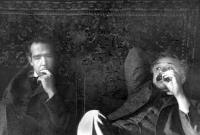
[Niels Bohr] contemplates one of [Einstein’s] many challenges to quantum theory.For more than a century it was thought that light was a wave. In 1801, [Thomas Young] had discovered interference patterns when shining a light through two very close slits. Interference is a well known property of waves. This combined with [Maxwell’s] equations, which predicted the existence of electromagnetic radiation put little doubt into anyone’s mind that light was nothing more, or less, than a wave. There was a very odd issue, however, that puzzled physicists during the 18th century. When shining light upon a metallic surface, electrons would be ejected from that surface. Increasing the intensity of the light did not translate to an increase in speed of the expelled electrons, like classical mechanics says it should. Increasing the frequency of the light did increase the speed. The explanation of this phenomenon could not be had until 1900, when [Max Planck] realized that physical action could not be continuous, but must be a multiple of some small quantity. This quantity would lead to the “quantum of action”, which is now called [Planck’s] constant and birthed quantum physics. It would have been impossible for him to know that this simple idea, in less than two decades, would lead to a change in understanding of the nature of reality. It only took Einstein, however, a few years to use [Planck’s] quantum of action to explain that mind-boggling issue of electrons releasing from metal via light and not following classical law with the incredibly complex equation:
E = hv
Where E is the energy of the light quanta, h is Planck’s constant and v is the frequency of the light. The most important item to consider here is this light quanta, later to be called a photon. It is treated as a particle. Now, if you’re not scratching your head in confusion right about now, you haven’t been paying attention. How can light be a wave and a particle? Join me after the jump and we’ll travel further down this physics rabbit hole.
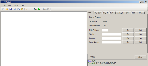
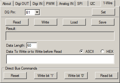
[CWroos] has written an impressive GUI for the Flyfish FF32. The Flyfish is a port expander of sorts, allowing the user access to a large array of I/O , analog inputs, SPI, I2C and a few other connectivity options over a USB connection. There is no driver as it uses a native HID driver in the operating system of the device it’s attached to. It’s not just tethered to a PC either. It works with Raspberry Pi, Beaglebone and several other SBCs.
[CWroos]’s GUI makes it easier than ever to interact with the FF32. It has a script editor allowing you to run and edit scripts on the fly (pun intended). It appears he’s actually written his own basic like language for the scripting, which he goes into great detail on his site. There’s a blinky script example, and few more complex examples that will show you how to read temperature and control a servo.
There is also the ability to control the hardware directly allowing you to set pins, read firmware version, set the USB address and several other options. If you have an FF32 lying around, be sure to check out [CWroos]’s program and let us know how it works for you.
This one’s crazy… literally one electronic device is talking to another. In spoken English. And it works.
We’ve covered several hacks for the Amazon Echo, but some might be surprised to learn that there is another piece of interesting hardware that comes along with it – a remote control. Wire in a Raspberry Pi to it, and you’ve given yourself a way to automate control of the Echo without ever taking the Echo itself apart. [Gamaral] did just this and gave his Echo some significantly enhanced capabilities.
He started off by identifying the power rails of the remote. Then he wires in a 3.3v voltage regulator and uses a 100 ohm resistor as a voltage divider to bring it down to the 1.8 volt logic level used by the Echo remote. A single wire runs from the Raspi GPIO to one of the tactile switches on the controller.
For software, the Raspi is running RPi buildroot with Espeak and a cron scheduler compiled in. This allows him to send commands to the Echo which makes it say just about anything he wants. But any voice commands accepted by the Echo should work. If you want to go outside of those boundaries check out the method of spoofing WeMo devices we saw the other day.
Be sure to check out the [gamaral’s] entertaining video below to see the hack in action.
Speak with those who consider themselves hardcore engineers and you might hear “Arduinos are for noobs” or some other similar nonsense. These naysayers see the platform as a simplified, overpriced, and over-hyped tool that lets you blink a few LEDs or maybe even read a sensor or two. They might say that Arduino is great for high school projects and EE wannabes tinkering in their garage, but REAL engineering is done with ARM, x86 or PICs. Guess what? There are Arduino compatible boards built around all three of those architectures. Below you can see but three examples in the DUE, Galileo, and Fubarino SD boards.
Arduino DUE uses Atmel ARM
Arduino Galileo uses Intel x86
Fubarino SD uses PIC32
This attitude towards Arduino exists mainly out of ignorance. So let’s break down a few myths and preconceived biases that might still be lurking amongst some EEs and then talk about Arduino’s ability to move past the makers.
Arduino is NOT the Uno
When some hear “Arduino”, they think of that little blue board that you can plug a 9v battery into and start making stuff. While this is technically true, there’s a lot more to it than that.
An Arduino Uno is just an AVR development board. AVRs are similar to PICs. When someones says “I used a PIC as the main processor”, does that mean they stuck the entire PIC development board into their project? Of course not. It’s the same with Arduino (in most cases), and design is done the same way as with any other microcontroller –
Use the development board to make, create and debug.
When ready, move the processor to your dedicated board.
What makes an Arduino an “Arduino” and not just an AVR is the bootloader. Thus:
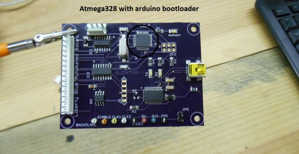
An Atmega328P is an AVR processor.
An Atmega328P with the Arduino bootloader is an Arduino.
The bootloader allows you to program the AVR with the Arduino IDE. If you remove the bootloader from the AVR, you now have an AVR development board that can be programmed with AVR Studio using your preferred language.
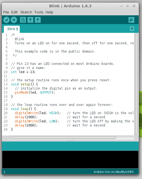
There Is No Special Arduino Language
Arduino “blink” sketch should run on any Arduino compatible board.
Yes, I know they call them sketches, which is silly. But the fact is it’s just c++. The same c++ you’d use to program your PIC. The bootloader allows the IDE to call functions, making it easy to code and giving Arduino its reputation of being easy to work with. But don’t let the “easy” fool you. They’re real c/c++ functions that get passed to a real c/c++ compiler. In fact, any c/c++ construct will work in the Arduino IDE. With that said – if there is any negative attribute to Arduino, it is the IDE. It’s simple and there is no debugger.
The strength comes in the standardization of the platform. You can adapt the Arduino standard to a board you have made and that adaptation should allow the myriad of libraries for Arduino to work with your new piece of hardware. This is a powerful benefit of the ecosystem. At the same time, this easy of getting things up and running has resulted in a lot of the negative associations discussed previously.
So there you have it. Arduino is no different from any other microcontroller, and is fully capable of being used in consumer products along side PICs, ARMs etc. To say otherwise is foolish.
What is the Virtue of Arduino in Consumer Products?
This is Ask Hackaday so you know there’s a question in the works. What is the virtue of Arduino in consumer products? Most electronics these days have a Device Firmware Upgrade (DFU) mode that allows the end user to upgrade the code, so Arduino doesn’t have a leg up there. One might argue that using Arduino means the code is Open Source and therefore ripe for community improvements but closed-source binaries can still be distributed for the platform. Yet there are many products out there that have managed to unlock the “community multiplier” that comes from releasing the code and inviting improvements.
What do you think the benefits of building consumer goods around Arduino are, what will the future look like, and how will we get there? Leave your thoughts below!
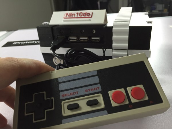
If your living room entertainment area is not home to a Raspberry Pi based retro game console, you no longer have any excuses. Break out your soldering iron and volt/ohm meter and preheat the 3d printer, because you will not be able to resist making one of the best retro game consoles we’ve ever seen – The Nin10do.
It’s creator is [TheDanielSpies]. Not only did he make the thing from scratch, he’s done an extraordinary job documenting all the build details, making it easier than ever to follow in his footsteps and make one of your own. He designed the case in Autodesk and printed it out with XT Co-polyester filament. He uses a Raspi of course, along with an ATX Raspi board from Low Power Labs to make the power cycling easier. There’s even a little stepper that opens and closes a cover that hides the four USB ports for controllers. Everything is tied together with Python, making the project super easy to modify and customize to your liking.
All code, schematics and .stl files are available on his github. It even has its own Facebook page! Be sure to check out the vast array of videos to help you along with your build.
[Shockwaver] stumbled across some old kerosene lanterns, and decided he also stumbled across his next project. He decided to leave the kerosene out, and in its place used some RGB LEDs to bring the lanterns back to life. This is quite an upgrade. Considering the burning kerosene will only put out a few colors of light, the astute reader will have realized the RGB array has the ability put out over 16 million colors.
After some initial testing, he settled on a 24 LED circle array powered by an ATtiny85. The FastLED library helped him keep the code within the tight memory requirements. [Shockwaver] was not used to working with the such a small amount of memory, but after some fiddling he was able to make it work in the end, using 8,126 bytes.
The source can be found on his github page. Be sure to check out the video below to see the RGB lantern in action.