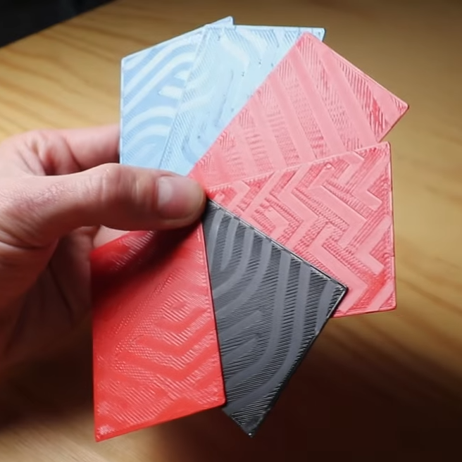
It used to be a rite of passage to be able to do the math necessary to design various bipolar transistor amplifier configurations. This doesn’t come up as often as it used to, but it is still a good skill to have, and [Void Electronics] walks us through a common emitter amplifier in a recent video you can see below.
The input design parameters are the gain and the collector voltage. You also have to pick a reasonable collector current within the range for your proposed device that provides enough power to the load. You also pick a quiescent voltage which, if you don’t have a good reason for picking a different value, will usually be half the supply voltage.
The calculations are approximate since the base-emitter voltage drop will vary by temperature, among other things. But, of course, real resistors won’t have the exact values you want, or even the exact value marked on them, so you need a little flexibility, anyway.
Variable capacitors may be useful, but the air gap that provides their capacitance is their greatest weakness. Rather than deal with the poor dielectric properties of air, some high-end variable capacitors replace it with a vacuum, which presents some obvious mechanical difficulties, but does give the resulting capacitor a remarkable quality factor, high-voltage performance, and higher capacitance for plate area than their air-gapped brethren. [Shahriar] of [The Signal Path] managed to acquire a pair of these and took a detailed look at their construction and performance in a recent video.
At the risk of starting a controversy: is there anyone who goes to the effort of setting up Home Assistant who wouldn’t really rather be living on the Enterprise-D? If such a person exists, it’s not [steve-gibbs5], who has not only put together a convincing LCARS dashboard on an Android tablet, but has also put together an easy-to-follow Instructable so you can too.
EDM (Electrical Discharge Machining) is one of those specialised manufacturing processes that are traditionally expensive and therefore somewhat underrepresented in the DIY and hacker scenes. It’s with great delight that we present EnderSpark, a solution to not one but two problems. The first problem is how to perform CNC operations on hard-to-machine materials such as hardened metals (without breaking the bank). The second problem is what to do with all those broken and forgotten previous-generation Creality Ender 3D printers we know you have stashed away.
To be honest, there isn’t much to a cheap 3D printer, and once you ditch the bed and extruder assembly, you aren’t left with a lot. Anyway, the first job was to add a 51:1 reduction gearbox between the NEMA 17 motors and the drive pullies, giving the much-needed boost to positional accuracy. Next, the X and Y axes were beefed up with a pair of inexpensive MGN12H linear rails to help them cope with the weight of the water bath.
At some point during our primary school careers, most of us probably constructed a simple compass, often by floating a magnetized needle on a cork in a cup of water. The water in such a configuration not only lets the needle spin without friction, but also dampens out (so to speak) the needle’s tendency to swing back and forth across the north-south line. Liquid-filled compasses use the same principle, but even well-made compasses can develop bubbles when exposed to temperature or pressure variations. Rather than accept this unsightly state of affairs, [The Map Reading Company] designed a new kind of liquid-free, inductively-damped compass.
It’s hard to design a compass that settles quickly, even if it uses a strong magnet, because the Earth’s own magnetic field is just so weak, and the stronger the internal magnet is, the more likely it is to be thrown off by nearby magnetic objects. As a result, they tend to swing, overshoot, and oscillate around their final orientation for some time. Most compasses use liquid to damp this, but a few, mostly military compasses, use a conductive baseplate instead: as the magnet moves, it induces eddy currents in the baseplate, which create a weak magnetic field opposing its motion, slowing the magnet down. Inductively-damped compasses don’t get bubbles, but they don’t let you see a map through the baseplate. [The Map Reading Company] dealt with this by making the baseplate transparent and surrounding the compass needle with a ring of high-conductivity copper alloy. This gave him a clear baseplate compass for easy map reading which would never develop bubbles. It’s a simple hack, and should be easy to replicate, but it still seems to be a new design. In fact, [The Map Reading Company] is releasing most of the design to the public domain. Anyone can build this design.
If this prompts your interest in compasses, check out the Earth inductor compass. We’ve also seen a visualization of the eddy currents that damp these oscillations, and even seen them used to drive a bike.
Continuing his reverse-engineering of the Intel 8087, [Ken Shirriff] covers the conditional tests that are implemented in the microcode of this floating point processing unit (FPU). This microcode contains the details on how to perform the many types of specialized instructions, like cos and arctan, all of which decode into many microcode ops. These micro ops are executed by the microcode engine, which [Ken] will cover in more detail in an upcoming article, but which is effectively its own CPU.
Conditional instructions are implemented in hardware, integrating the states of various functional blocks across the die, ranging from the instruction decoder to a register. Here, the evaluation is performed as close as possible to the source of said parameter to save on wiring.
Implementing this circuitry are multiplexers, with an example shown in the top die shot image. Depending on the local conditions, any of four pass transistors is energized, passing through that input. Not shown in the die shot image are the inverters or buffers that are required with the use of pass transistors to amplify the signal, since pass transistors do not provide that feature.
Despite how firmly obsolete the 8087 is today, it still provides an amazing learning opportunity for anyone interested in ASIC design, which is why it’s so great that [Ken] and his fellow reverse-engineering enthusiasts keep plugging away at recovering all this knowledge.
[Ronan] likes 35mm film photography, but the world, of course, has gone digital. He picked up an Epson FilmScan 200 for about €10. This wonder device from 1997 promised to convert 35mm film to digital at 1200 DPI resolution. But there was a catch: it connects via SCSI. Worse, the drivers were forever locked to Windows 95/98 and Mac System 7/8.
In a surprise twist, though, [Ronan] recently resurrected a Mac SE/30 with the requisite SCSI port and the System 7 OS. Problem solved? Not quite. The official software is a plugin for Photoshop. So the obvious answer is to write new software to interact with the device.