7 LED’s, 2 Pins – Beat That, Charlieplexing

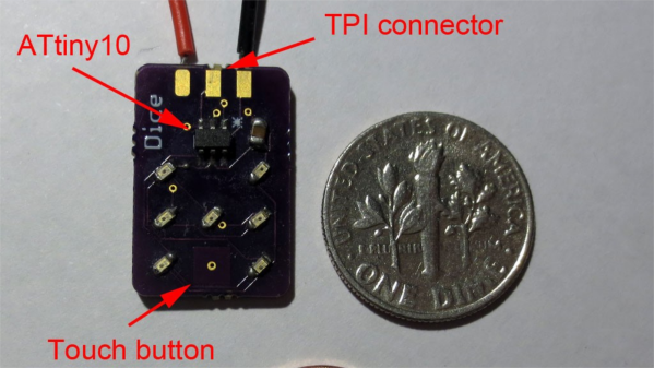
[Tim]’s Dice10 is an exercise in minimalism. Building an electronic dice using an ATtiny10 with code that fits within 1kB is not too difficult. Charlieplexing the LED’s would have used three of the four available GPIO pins. [Tim] upped the game by using just two GPIO pins to drive the seven LED’s for the dice. A third GPIO is used as a touch button input. Besides the ATtiny and the LED’s, the only other component used is a capacitor across the supply inputs.
2 GPIO for 7 LED's
2 GPIO for 7 LED’s

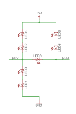
The LED’s are grouped in three pairs of two LED’s and a single centre LED. Usually, Charlieplexed LED’s are connected across pairs of GPIO pins. But his scheme includes connections to the 5V and GND terminals, besides the two GPIO pins. Building a truth table makes it easy to figure out what’s going on.

STATE PB2 PB0 LED's
1     Z   Z   --
2     L   Z   LED 1/2
3     H   Z   LED 3/4
4     Z   L   LED 5/6
5     Z   H   --
6     H   L   LED9
7     L   H   --
8     H   H   --
9     L   L   --

Only the logic states used are listed in the table. It’s possible to add two more LED’s between PB0 and GND and one more anti-parallel with LED9, making a total of 10 LED’s driven by two pins. That’s quite a hack. The important thing here is to have two LED’s in series in the arms that connect to either 5V or GND.

[Tim] has posted  the code and hardware source files on his Github repo, and his blog post has some additional details on how he solved the problem.

If you’re looking for more inspirations on minimal dice designs, check this “PIC powered pair of electronic dice” which uses a PIC 12F629 with five outputs driving a pair of 7 pips to make a dual dice.

1kb-thumb

If you have a cool project in mind, there is still plenty of time to enter the 1 kB Challenge! Deadline is January 5, so check it out and fire up your assemblers!

Another Way To Look At Charlieplexing

Charlieplexing is a technique that allows you to drive a larger number of LEDs than wouldn’t be possible with the same number of I/O pins on a traditional multiplexed matrix. If we lost you there just think of it as lots of blinky lights connected to a small number of pins. It works by leveraging the one-way nature of a diode. Current will only flow through an LED in one direction so if you hook up your display in a clever way you can drive multiple LEDs from one I/O by switching the polarity of that pin between voltage and ground. [M.Rule] recently looked at using Charlieplexing with LED modules. His conceptual approach to the problem is different from those we remember seeing before and it’s worth a look.

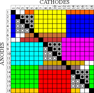
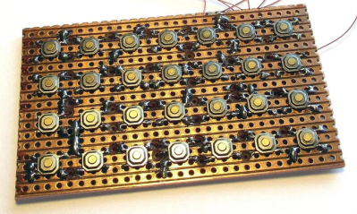
Instead of just using the formula to calculate how many LEDs he can drive [M.Rule] is using a table of I/O pins to establish how many and in what order these displays can be connected. Each colored set of blocks represents an LED module. The graphic above shows how 18-pin can be utilized. He even filled in the unused pin combinations with input buttons.

Improve Charlieplexing Performance With Interrupts

single_chip_led_matrix

[Dmitry] was shopping for LEDs and accidentally pulled the trigger on the wrong type. Since he didn’t want to be wasteful, he figured he should at least take the time to build something with them.

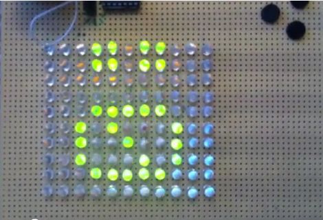
A LED matrix display was the obvious project choice, but he only had a PIC16F688 at his disposal. Since the micro controller only has 11 output pins, charlieplexing was the only way he would be able to light the entire matrix.

While testing his LED array, he found charlieplexing to be a bit disappointing. The fact that the LEDs can get relatively dim, depending on the number of units lit at any particular time struck him as annoying.

In order to improve the performance of his charlieplexed array, he first decided to scan through all of the LEDs rather than just those that needed to be lit. This ensured that all of his LEDs had the same 1/110 duty cycle and were always as bright as possible. He also chose to use interrupts when lighting the LEDs. This meant that his code does not need to take into consideration any specific timing requirements to maintain persistence of vision. He also double-buffers the display to help reduce flicker.

He says that he ran into certain constraints with the PIC chip he chose, so he used a handful of lookup tables to ensure smooth operation of his display. He was quite satisfied with the results, and we think that the interrupt-driven display looks like it works just fine from where we’re standing as well.

Be sure to stick around for a quick video explaining and demonstrating his single-chip LED matrix.

Continue reading “Improve Charlieplexing Performance With Interrupts”

Intro To Charlieplexing

charlie

[sixerdoodle] sent us this nice firefly project that serves as an intro to charlieplexing. We’ve mentioned charlieplexing before, in our LED Life post and the Breath Controlled LED candles post. This project is quite simple and focues mainly on how to make a charlieplexed circuit work.

The goal was to create a tiny firefly bottle with SMD LEDs and as few wires as possible. In the video, after the break, it is hard to tell just how small this thing is until we see the battery. There are clear directions and fantastic pictures detailing exactly how to set up a charlieplexed circuit with 6 LEDs.

Continue reading “Intro To Charlieplexing”

LED Life And Charlieplexing


Yesterday, we featured [Andrew]’s orientation aware camera. We want to highlight another one of his projects: LED Life. It’s a 6×5 LED matrix playing Conway’s Game of Life. He used the low power MSP430 like our e-paper clock. The best part of the writeup is his explanation of how Charlieplexing works. Microcontroller GPIO pins generally have three possible states: output high, output low, and input. This combined with the directional nature LEDs and some creative wiring means you can run a large matrix of individually addressable LEDs with just a few IO pins. Instead of just flipping the IO pins on and off you change their assigned state. Have a look at [Andrew]’s site for some great illustrations of how the system works. A video of his LED Life board is embedded below. Continue reading “LED Life And Charlieplexing”

ACK1 Makes Getting To Know The ATtiny1616 Easy

Many readers will be familiar with Microchip’s ATtiny85, which has been a popular choice for DIY projects in the past for its low price and (for the time) small size. But those looking for a more modern and capable 8-bit chip may find the ATtiny1616-MNR of interest. It offers expanded flash storage, more GPIO, and ditches SPI programming in favor of UPDI — a protocol that can be done using nothing more than an USB-UART converter and a resistor.

The contents of the ACK1 kit
What’s in the kit if you buy it.

But here’s the catch: the new chip is only available in SMD and there are far fewer tutorials for it! That’s why [Bradán Lane] has created ACK1, a cute little AVR Coding Kit for those of us who want to play with the ATtiny1616 and a companion for his free and open-source course.

The board contains an array of 6 by 7 LEDs in a charlieplexed configuration, a large piezo buzzer, two push buttons, an on/off switch, and a CR2032 battery holder to keep it on without the need for a cable. The kit looks gorgeous in its white-on-black theme with gold plated contacts and can be had for $20 on Tindie at the time of writing.

The ATtiny1616 itself runs at up to 20 MHz and has 17 GPIO pins, 16 KiB of flash storage, 2 KiB of RAM, and 256 bytes of EEPROM for configuration — making it roughly on par with the original Arduino Uno.

The course that goes hand-in-hand with the ACK1 is all about the features of the ATtiny1616, from the basics of using the programmer to reading the buttons, using timers, driving the charlieplexed LEDs, storing data in the EEPROM and much more. Though it does not cover the basics of C, the course is free, and even licensed MIT, so that anyone can share it and improve upon it.

If you enjoy seeing beautiful microcontrollers, you’ll definitely want to see the stylish Uno Plus+.

Blinky Business Card Plays Snake And Connect Four

There’s no better way to introduce yourself than handing over a blinky PCB business card and challenging the recipient to a game of Connect Four. And if [Dennis Kaandorp] turns up early for a meeting, he can keep himself busy playing the ever popular game of Snake on his PCB business card.

The tabs are 19 mm long and 4 mm wide.

Quite wisely, [Dennis] kept his design simple, and avoided the temptation of feature creep. His requirements were to create a minimalist, credit card sized design, with his contact details printed on the silk legend, and some blinky LED’s.

The tallest component on such a design is usually the battery holder, and he could not find one that was low-profile and cheap. Drawing inspiration from The Art of Blinky Business Cards, he used the 0.8 mm thin PCB itself as the battery holder by means of flexible arms.

Connect-Four is a two player game similar to tic-tac-toe, but played on a grid seven columns across and six rows high. This meant using 42 dual-colour LED’s, which would require a large number of GPIO pins on the micro-controller. Using a clever combination of matrix and charlieplexing techniques, he was able to reduce the GPIO count down to 13 pins, while still managing to keep the track layout simple.

It also took him some extra effort to locate dual colour, red / green LED’s with a sufficiently low forward voltage drop that could work off the reduced output resulting from the use of charlieplexing. At the heart of the business card is an ATtiny1616 micro-controller that offers enough GPIO pins for the LED matrix as well as the four push button switches.

His first batch of prototypes have given him a good insight on the pricing and revealed several deficiencies that he can improve upon the next time around. [Dennis] has shared KiCad schematic and PCB layout files for anyone looking to get inspired to design their own PCB business cards.

Continue reading “Blinky Business Card Plays Snake And Connect Four”