LED lighting is now commonplace across homes, businesses, and industrial settings. It uses little energy and provides a great deal of light. However, a new study suggests it may come with a trade-off. New research suggests human vision may not perform at its peak under this particular form of illumination.
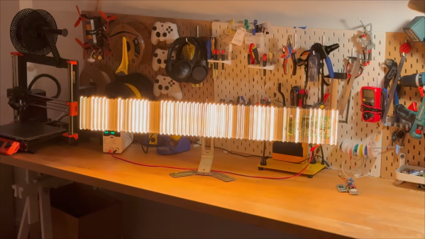
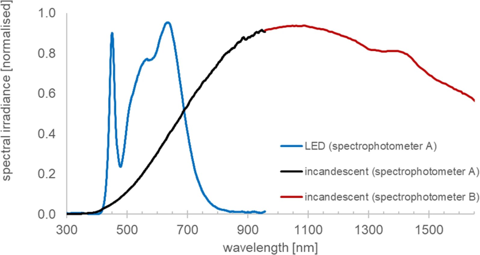
The study ran with a small number of subjects (n=22) aged between 23 to 65 years. They were tested prior to the study for normal visual function and good health. Participants worked exclusively under LED lighting, with a select group then later also given supplemental incandescent light (with all its attendant extra wavelengths) in their working area—which appears to have been a typical workshop environment.
Notably, once incandescent lighting was introduced, those experimental subjects showed significant increases in visual performance using ChromaTest color contrast testing. This was noted across both tritan (blue) and protan (red) axes of the test, which involves picking out characters against a noisy background. Interestingly, the positive effect of the incandescent lighting did not immediately diminish when those individuals returned to using purely LED lighting once again. At tests 4 and 6 weeks after the incandescent lighting was removed, the individuals continued to score higher on the color contrast tests. Similar long-lasting effects have been noted in other studies involving supplementing LED lights with infrared wavelengths, however the boost has only lasted for around 5 days.
The exact mechanism at play here is unknown. The study authors speculate as to a range of complex physical and biological mechanisms that could be at play, but more research will be needed to tease out exactly what’s going on. In any case, it suggests there may be a very real positive effect on vision from the wider range of wavelengths provided by good old incandescent bulbs. As an aside, if you’ve figured out how to get 40/40 vision with a few cheap WS2812Bs, don’t hesitate to notify the tip line.
Thanks to [Keith Olson] for the tip!