RGB LED Cylinder

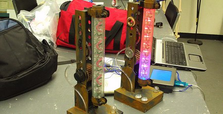
[Dave Clausen] from NYC Resistor sent in his open source RGB LED cylinder. We have seen many cubes in the past (even one that display low-res 3D video) so a cylinder is certainly a new concept and the RGB LEDs are a nice upgrade. The LEDs are wired in a 5-way multiplexed grid using four TLC5940NTs (16 channel LED drivers with internal PWM hardware) so each light is individually addressable. The best thing about this project, of course, is that he has source and EAGLE schematics availbale for download and both are licensed under Creative Commons.

[via NYC Resistor]

Maker Faire 2008: ShiftBright RGB LED Module


We made a point to stop by [garrett]’s booth at Maker Faire to to see what he had been working on. You may remember him from his random caps locker shenanigans. He’s just recently released the ShiftBright RGB LED module which makes it easy to implement a string of individually addressable LEDs. The module is based on the Allegro A6281 3-Channel Constant Current LED Driver. The driver chip is capable of displaying a billion colors using an RGB LED. The 3x3mm package is mounted to the backside of the board while a bright common-anode RGB is mounted to the front. The modules are designed to be daisy chained together and are individually addressed using a serial interface. You can find Arduino example code on the site and more info on how the item was developed. Read on for close up images.

Continue reading “Maker Faire 2008: ShiftBright RGB LED Module”

Slim RGB Matrix Puts LEDs Inside The PCB

Sometimes all that’s required to build something interesting is to put the same old pieces together differently. [Sayantan Pal] did this for the humble RGB LED matrix, creating an extra-thin version by recessing WS2812b NeoPixel LEDs inside a PCB.

The popular WS2812B is 1.6 mm in height, which happens to be the most commonly used PCB thickness. Using EasyEDA, [Sayantan] designed a 8×8 matrix with modified WS2812B footprints. A slightly undersized cutout was added to create a friction-fit for the LEDs, and the pads were moved to the back side of the panel just outside the cutout, and their assignment were flipped. The PCB is assembled face down, and all the pads are soldered by hand. Unfortunately this creates rather large solder bridges which slightly increases the overall thickness of the panel, and is probably also unsuitable for production with conventional pick-and-place assembly.

We’ve seen some similar methods with PCB assemblies that use layered PCBs. Manufacturers are starting to even embed components inside multilayer PCBs.

Gyro Controlled RGB Blinky Ball Will Light Up Your Life

[James Bruton], from the XRobots YouTube channel is known for his multipart robot and cosplay builds. Occasionally, though, he creates a one-off build. Recently, he created a video showing how to build a LED ball that changes color depending on its movement.

The project is built around a series of 3D printed “arms” around a hollow core, each loaded with a strip of APA102 RGB LEDs. An Arduino Mega reads orientation data from an MPU6050 and changes the color of the LEDs based on that input. Two buttons attached to the Mega modify the way that the LEDs change color. The Mega, MPU6050, battery and power circuitry are mounted in the middle of the ball. The DotStar strips are stuck to the outside of the curved arms and the wiring goes from one end of the DotStar strip, up through the middle column of the ball to the top of the next arm. This means more complicated wiring but allows for easier programming of the LEDs.

Unlike [James’] other projects, this one is a quickie, but it works as a great introduction to programming DotStar LEDs with an Arduino, as well as using an accelerometer and gyro chip. The code and the CAD is up on Github if you want to create your own. [James] has had a few of his projects on the site before; check out his Open Dog project, but there’s also another blinky ball project as well.

Continue reading “Gyro Controlled RGB Blinky Ball Will Light Up Your Life”

Driving RGB Pixel LEDs With CAT5 Cable

cable-test

[Teknynja] was working on a project where he needed to drive a few strips of Adafruit Neopixels – WS2812 LED strips – that were located several feet apart. These LED strips draw a lot of current, and are very timing sensitive; anything more than a few feet of wire between the microcontroller and the LED strip will probably result in missed data, voltage drops, dimming LEDs, and possibly a non-functional strip.

The solution, as in all matters concerning long distance transmission of data, was CAT5 cable. [Teknynja] used RS-422 drivers and receivers to pull this task off, with 75174 line drivers receiving signals from a Teensy 3.0, and 75176 bus transceivers reading everything at the other end of a 20 foot cable.

For the power drop issue, [Teknynja] is feeding 12V into a few of the wire pairs in the cable and using a cheap  LM2596 buck converter to step everything down to 5V at the strip.

With a fairly simple circuit, [Teknynja] was able to drive a few strips of WS2812 LEDs through 20-foot lengths of CAT5 cable with ease; it worked just the same as if the pixels were connected directly to the Teensy on a workbench.

Android Controlled RGB Lights

ScreenShot032

Here’s a handy hack for an Android controlled, Arduino driven, RGB light setup.

[Kerimil] recently wrote up this project on the Arduino.cc, and is sharing all of the source code and plans. While many of our seasoned Arduino-lovers can easily throw together the code for an RGB LED circuit in their sleep, [Kerimil] also threw in the Android app, and the source file to be modified in App Inventor, an Android app development program originally released by Google, but now maintained by MIT.

We’ve seen many commercial versions of this product, but it’s nice to see one that can be easily hacked to our liking. Next up is writing an app to use the phone’s camera to identify colors and reproduce them with the LED! While you’re at it, why not mix it with an easy to build infinity mirror!

To see the board and app in action, check out the video after the break.

Continue reading “Android Controlled RGB Lights”

Disco Planet, A Massive RGBW LED Array In A 6′ Globe

About half a year ago [John] over at Frank’s Kitchens came to me with an idea for a giant lighting project. He had this 6ft diameter aluminum frame globe rescued from the Philadelphia Theater Company and wanted it to be an interactive display of sorts. After a few discussions we got together and somehow managed to order 800 3 watt LEDs in red, green, blue, and white. We had a system that worked great on paper, and managed to get it built by Valentines day for a big show. It failed miserably and hardly even illuminated the LEDs. I, naturally, took this far too personally and set out for a complete redesign, looking in the direction of digitally addressable LED strips.

In addition to building a crazy turbo charged LED array I also spent a lot (a whole lot) of time coding a nice clean fully functioning RGB LED strip controller using an Arduino Pro Mini (5V 16 MHz), the MSGEQ7 audio frequency multiplexer (PDF) , and an IR remote. I plan on using this for other projects so the code can be easily reconfigured to use many different LED strips and a whole slew of IR remotes.

The schematic of the globe is here. The top half  of that schematic be catered to other projects using a variety of pre-built LED strips. The pastebin with code is here,  fastSPI_LED and IRRemote here and here. Some code jockeying was required to get IRRemote.h and FastSPI_LED to play nicely together, so check the code comments.

Continue reading “Disco Planet, A Massive RGBW LED Array In A 6′ Globe”