AI agents are learning to do all kinds of interesting jobs, even the creative ones that we quite prefer handling ourselves. Nevertheless, technology marches on. Working in this area is YouTuber [AI Warehouse], who has been teaching an AI to walk in a simulated environment.
The AI controls a vaguely humanoid-like creature, albeit with a heavily-simplified body and limbs. It “lives” in a 3D environment created in the Unity engine, which provides the necessary physics engine for the work. Meanwhile, the ML-Agents package is used to provide the brain for Albert, the AI charged with learning to walk.
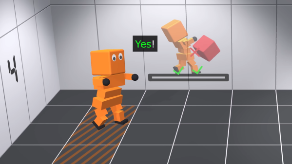
The video steps through a variety of “deep reinforcement learning” tasks. In these, the AI is rewarded for completing goals which are designed to teach it how to walk. Albert is given control of his limbs, and simply charged with reaching a button some distance away on the floor. After many trials, he learns to do the worm, and achieves his goal.
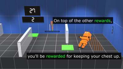
Getting Albert to walk upright took altogether more training. Lumpy ground and walls in between him and his goal were used to up the challenge, as well as encouragements to alternate his use of each foot and to maintain an upright attitude. Over time, he was able to progress through skipping and to something approximating a proper walk cycle.
One may argue that the teaching method required a lot of specific guidance, but it’s still a neat feat to achieve nonetheless. It’s altogether more complex than learning to play Trackmania, we’d say, and that was impressive enough in itself. Video after the break.