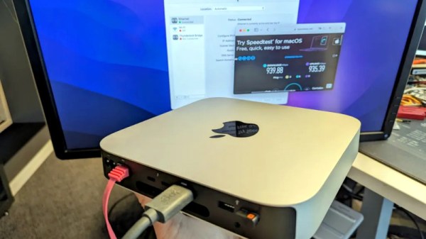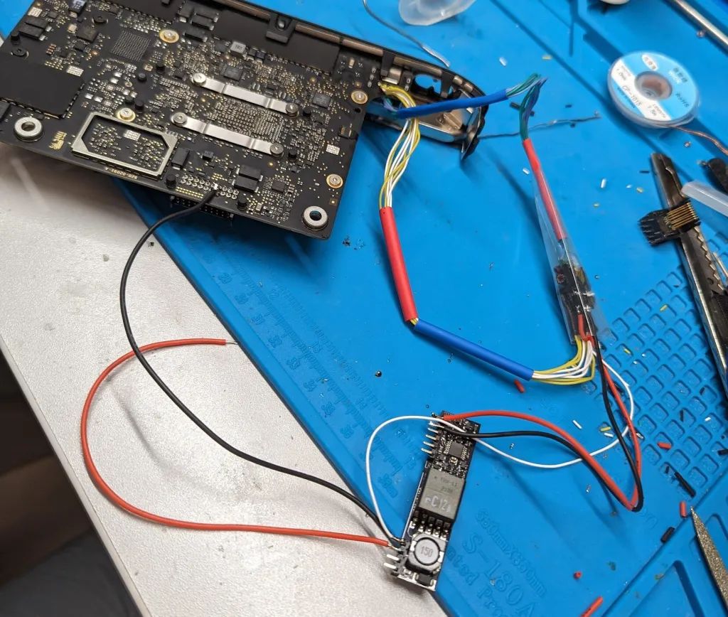
Internet connectivity in remote areas can be a challenge, but recently SpaceX’s Starlink has emerged as a viable solution for many spots on the globe — including the Ukrainian frontlines. Unfortunately, in 2021 Starlink released a new version of their hardware, cost-optimized to the point of losing some nice features such as the built-in Ethernet RJ45 (8P8C) port, and their proposed workaround has some fundamental problems to it. [Oleg Kutkov], known for fixing Starlink terminals in wartime conditions, has released three posts on investigating those problems and, in the end, bringing the RJ45 ports back.
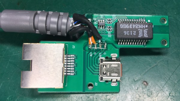
Starlink now uses an SPX connector with a proprietary pinout that carries two Ethernet connections at once: one to the Dishy uplink, and another one for LAN, with only the Dishy uplink being used by default. If you want LAN Ethernet connectivity, they’d like you to buy an adapter that plugs in the middle of the Dishy-router connection. Not only is the adapter requirement a bother, especially in a country where shipping is impeded, the SPX connector is also seriously fragile and prone to a few disastrous failure modes, from moisture sensitivity to straight up bad factory soldering.
Continue reading “Restoring Starlink’s Missing Ethernet Ports”