Join us Wednesday at noon Pacific time for the Home Machine Shop Hack Chat!
Even if you haven’t been here for very long, you’ll probably recognize Quinn Dunki as Hackaday’s resident consulting machinist. Quinn recently did a great series of articles on the “King of Machine Tools”, the lathe, covering everything from the history of precision machine tools to making your first chips. She’s documented the entire process of procuring and setting up a new lathe, pointing out all the potential pitfalls the budding home machinist may face. You can get a much deeper dive into her machining adventures on her YouTube channel, Blondihacks.
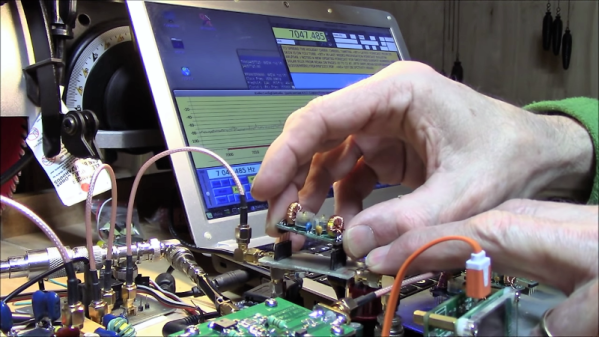
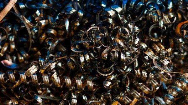
Flinging hot metal chips around is hardly all Quinn has accomplished, though. Long before her foray into machine tools, there was Veronica, a scratch-built 6502 machine Quinn created as an homage to the machines that launched her into a life of writing software. We’ve featured Veronica on our pages a couple of times, and she’s always made quite a hit.
Please join us for this Hack Chat, where we’ll discuss:
- How developing software and machining are alike, and how they differ;
- How social networks have changed the perception of machining;
- Best practices for getting started in machining; and
- Are there any new machine tool purchases in the pipeline?
You are, of course, encouraged to add your own questions to the discussion. You can do that by leaving a comment on the Home Machine Shop Hack Chat and we’ll put that in the queue for the Hack Chat discussion.
 Our Hack Chats are live community events on the Hackaday.io Hack Chat group messaging. This week we’ll be sitting down on Wednesday, March 20, at noon, Pacific time. If time zones have got you down, we have a handy time zone converter.
Click that speech bubble to the right, and you’ll be taken directly to the Hack Chat group on Hackaday.io. You don’t have to wait until Wednesday; join whenever you want and you can see what the community is talking about.