Hackaday Prize Entry: 10 Watt Individually Addressable RGB LEDs

Individually addressable RGB LEDs like Neopixels, WS2812s, and  WS2811s are the defacto standard for making blinkey glowey projects. To build a very bright display, you need a lot of them, relegating very bright RGB displays to those of us who can afford the hardware and figure out how to drive that many LEDs. For his Hackaday Prize entry, [AJ Reynolds] is cranking these tiny RGB LEDs up a notch by building an individually addressable 10 Watt RGB floodlight.

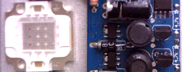
Instead of building an RGB LED floodlight from scratch, [AJ] is leveraging the most mediocre of what China has to offer. He found 10 Watt RGBs for a dollar a piece and a few floodlight cases that cost about $5 a piece. By dispensing with the white LED in the floodlight case and replacing it with a 10 Watt RGB LED and some custom circuitry, [AJ] can build a powerful RGB floodlight with a BOM cost of under $15.

While there are big RGB floodlights out there, controlling them either means a custom proprietary protocol or messing around with DMX. A floodlight that speaks the same language as a WS2811 leverages an enormous amount of work from the world of Arduino and a lot of projects from around the Internet, making this a great entry for really bright blinkies and an excellent entry for The Hackaday Prize.

The 2015 Hackaday Prize is sponsored by:

Polar Coordinate Mapping And RGB LED Disks

Last week, Adafruit released the DotStar RGB LED Disk, a 240mm diameter disk packed with 255 individually addressable RGB LEDs. Because blinkey glowey projects are the best projects, [Adam] had to have one. His tests open up some interesting possibilities in the world of blinkey LED stuff, including a polar coordinate display that would be perfect for low-res games and LED clocks.

[Adam] found the Disk sufficiently bright and glowey, but there were two problems. The first was the JST SM connector on the input of the DotStar Disk; with 255 LEDs on the disk, it has a maximum draw of over 10A, while the connector can only supply 7A without getting unreasonably warm. Secondly, there aren’t 60 LEDs around the outer edge of the disk, limiting its application as a clock.

There’s another thing wrong with the DotStar Disk, until you realize it’s effectively a polar coordinate display. RGB LED libraries are usually written for strips or matrices, not circles. The LEDs are sequentially arranged on the DotStar disk spiraling inwards, and after mucking about with some terrible code, [Adam] realized he could control a pixel with only its distance from center and angle from the connector. This makes plotting circles easier, but it also opens this display up to some interesting applications; circular Pong would be cool, and LED clocks are the bees knees.

The Possibility Of Driving 16,000 RGB LEDs

Like just about everyone we know, [Luis] decided a gigantic RGB LED matrix would be a cool thing to build. Gigantic LED matrices are very hard to build, though: not only do you have to deal with large power requirements and the inevitable problems of overheating, you also need to drive a boat load of LEDs. This is not easy.

[Luis] found a solution to the problem of driving these LEDs with a new, fancy ARM Cortex M4 microcontroller. All Cortex M4 ARMs have DMA, making automatic memory transfers to peripherals and LED strips a breeze.

The microcontroler [Luis] is using only supports 1024 transfers per transfer set, equating to a maximum of 14 LEDs per transfer. This problem can be fixed by using the ping-pong mode in the DMA controller by switching between data structures for every DMA request. Basically, he’s extending the number of LEDs is just switching between two regions of memory and setting up the DMA transfer.

The result is much better than [Luis]’ original circuit that was just a bunch of SPI lines. It also looks really good, judging by the video below. It’s not quite a gigantic LED matrix yet, but if you want to see what that would look like, check out the huge 6 by 4 foot matrix hanging in the Hackaday overlord office.

Continue reading “The Possibility Of Driving 16,000 RGB LEDs”

RGB LED Matrices With The STM32 And DMA

A few years ago, [Frans-Willem] bought a few RGB LED panels. Ten 32×16 panels is a lot of LEDs, and to drive all of these panels requires some sufficiently powerful hardware. He tried working with an FPGA development board, but that didn’t have enough memory for 24-bit color. The microcontroller du jour – a TI Stellaris – couldn’t get more than 16 bits of color without flickering. With a bunch of LEDs but no way to drive them, [Frans-Willem] put the panels in a box somewhere, waiting for the day they could be used to their fullest capacity.

This day came when [Frans-Willem] was introduced to the STM32 series of chips with the F1 Discovery board. While looking for some electronic playthings to use with this board, he stumbled upon the LED panels and gave them one more try. The results are spectacular, with 33 bits of color, with animations streamed over a router over WiFi.

The panels in question are HUB75 LED panels. In the 32×8 panels, there are six data pins – two each for each color – four row select pins, and three control pins. The row select pins select which row of pixels is active at any one time. Cycle through them fast enough, and it will seem like they’re all on at once. The control pins work pretty much like the control pins of a shift register, with the data pins filling in the obvious role.

The code that actually drives the LEDs all happens on an STM32F4 with the help of DMA and FSMC, or the Flexible Static Memory Controller found on the chip. This peripheral takes care of the control lines found in memory, so when you toggle the write strobe the chip will dump whatever is on the data lines to a specific address in memory. It’s a great way to take care of generating a clock signal.

For sending pixels to this display driver, [Frans-Willem] is using the ever-popular TP-Link WR703N. He had originally planned to send all the pixel data over the USB port, but there was too much overhead, a USB 1.1 isn’t fast enough. That was fixed by using the UART on the router with a new driver and a recompiled version of OpenWRT.

All the software to replicate this project is available on Github, and there’s a great video showing what the completed project can do. You can check that out below.

Continue reading “RGB LED Matrices With The STM32 And DMA”

Voice Controlled RGB LED Lamp

Voice Controlled Lamp

[Saurabh] wanted a quick project to demonstrate how easy it can be to build devices that are voice controlled. His latest Instructable does just that using an Arduino and Visual Basic .Net.

[Saurabh] decided to build a voice controlled lamp. He knew he wanted it to change colors as well as be energy-efficient. It also had to be easy to control. The obvious choice was to use an RGB LED. The LED on its own wouldn’t be very interesting. He needed something to diffuse the light, like a lampshade. [Saurabh] decided to start with an empty glass jar. He filled the jar with gel wax, which provides a nice surface to diffuse the light.

The RGB LED was mounted underneath the jar’s screw-on cover. [Saurabh] soldered a 220 ohm current limiting resistor to each of the three anodes of the LED. A hole was drilled in the cap so he’d have a place to run the wires. The LED was then hooked up to an Arduino Leonardo.

The Arduino sketch has several built-in functions to set all of the colors, and also fade. [Saurabh] then wrote a control interface using Visual Basic .Net. The interface allows you to directly manipulate the lamp, but it also has built-in voice recognition functionality. This allows [Saurabh] to use his voice to change the color of the lamp, turn it off, or initiate a fading routing. You can watch a video demonstration of the voice controls below. Continue reading “Voice Controlled RGB LED Lamp”

Visualize Vroom With This RGB LED Tachometer

[Pete Mills] recently bought the all-new Ford Fiesta, which offers impressive fuel economy over that of his Jeep. He soon figured out that he has real time access to a wealth of engine and chassis data through Ford’s OpenXC platform and used it to build blueShift, a neopixel tachometer. The car already has a tach, but this one is more visual, can be seen in periphery, and is just plain fun.

In case you hadn’t heard, the OpenXC platform is Ford’s consumer key to the kingdom of OBD2 treasures. It unlocks the magic through its Vehicle Interface, which plugs into the OBD2 port and translates the CAN bus messages to OpenXC format. These messages are packaged into JSON format and can be sent over Bluetooth or Ethernet/Wi-Fi to an Android, Python, or iOS device.

[Pete] went with Bluetooth and used a BlueSMiRF with an Arduino Pro Mini. He derives power from the car’s on-board USB port, but has future plans to use the OpenXC VI port. blueShift reads the RPM data and displays a green trail as the engine revs up. At the peak revolution, it shows a red LED. This one is sticky and will persist for the lesser of three seconds or the time elapsed to a new positive RPM. [Pete] is also reading the headlight status of the car. As soon as they come on, the RGB LEDs dim to avoid blinding him at night.

[Pete] wanted to make an enclosure more finished-looking than a Tupperware box. He nearly detoured into 3D-printer design, but ended up putting together a Prusa i3v and came up with this RAM mount-compatible enclosure. His fantastic write-up and code are on his blog, but you can make the jump to see a short demo and a full explanation video. You can also make smart brake lights or even create art with OpenXC.

Continue reading “Visualize Vroom With This RGB LED Tachometer”

Here Come The RGB LED Clones

ws2812 and clones timing

It seems like every third project on Hackaday uses WS2812 RGB LEDs in some way. We all love our blinkenlights, and bright, cheap, serial controlled RGB LEDs are the bees knees.

As with all products these days, competing manufacturers have discovered the huge market for these things, and clones are now available. [Tim] recently took a look at the PD9823, as well as three versions of the WS2812. [Tim] is considered something of a WS2812 guru here at Hackaday. You might remember him from his WS2812 driver optimization article, which should be required reading for any WS2812 hacker.

As many of us know, the timing characteristics for these LEDs can be a pain to work with. The values also differ between the WS2812S and WS2812B. [Tim] discovered that the new through hole WS2812D parts are different yet again, though rather close to the B parts. The PD9823’s designers must have studied the WS2812’s closely, as their 190ns time base falls directly between WS2812S 166ns time and the 208ns time of the WS2812B. The PD9823 also requires a slightly longer reset pulse.

The takeaway is that well written drivers such as [Tim’s] should have no problem with the new parts, but compatibility is something to keep in mind as more clones hit the market.