Because I often work with students, I’m always on the look-out for a simple CPU, preferably in Verilog, in the Goldilocks zone. That is, not too easy and not too hard. I had high hopes for this 16-bit RISC processor presented by [fpga4student], but without some extra work, it probably isn’t usable for its intended purpose.
The CPU itself is pretty simple and fits on a fairly long web page. However, the details about it are a bit sparse. This isn’t always a bad thing. You can offer students too much help. Then again, you can also offer too little. However, what was worse is one of the modules needed to get it to work was missing! You might argue it was an exercise left to the reader, but it probably should have been pointed out that way.
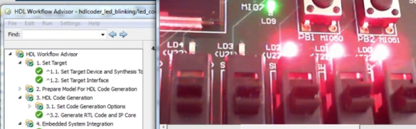
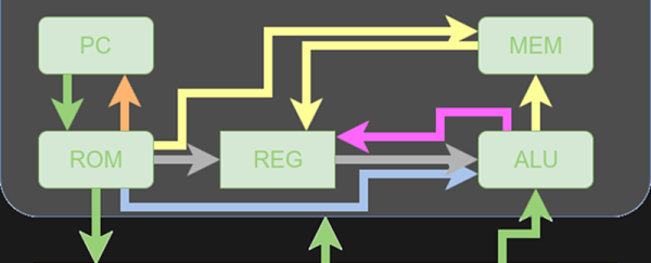
At first, I was ready to delete the bookmark and move on. Then I decided that the process of fixing this design and doing a little analysis on it might actually be more instructive than just studying a fully working design. So I decided to share my fix with you and look inside the architecture a bit more. On top of that, I’ll show you how to get the thing to run in an online simulator so you can experiment with no software installation. Of course, if you are comfortable with a Verilog toolchain (like the ones from Xilinx or Altera, or even free ones like Icarus or CVer) you should have no problem making that work, either. This time I’ll focus on how the CPU works and next time I’ll show you how to simulate it with some free tools. Continue reading “Learn By Fixing: Another Verilog CPU”
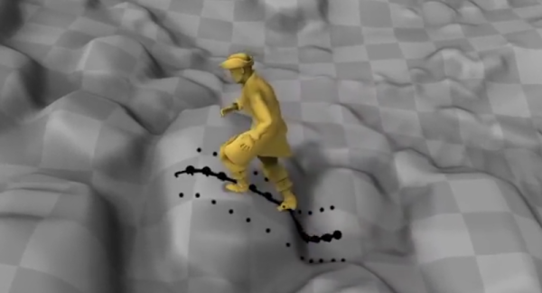
 To remedy the abrupt movements, [Daniel Holden et. al] recently