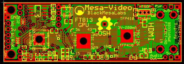
If you want video support on your project, you might start from a device like a Raspberry Pi that comes with it built in. [Kevinhub88] doesn’t accept such compromises, so he and his Black Mesa Labs have come up with a whole new way to add video support to devices like the Arduino and other cheap controllers. This project is called Mesa-Video, and it can add digital video at a resolution of up to 800 by 600 pixels to any device that has a single serial output.
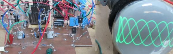
The video is created by an FT813, a low cost GPU from FTDI that offers a surprising amount of video oomph from a cheap, low power chip (he has demoed it running from a lemon battery), meaning that he is hoping to be able to sell the Mesa-Video for under $50.
UPDATE: [KevinHub88] let us know that he didn’t actually power the device from a lemon battery, as you would need a lot of lemons to make 50mA at 5V. Apologies for any confusion!
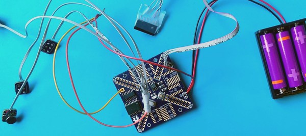
However, Mesa-Video is just the beginning. [Kevinhub88] wanted to get around the problem of stacking shields on Arduinos: add more than one and you get problems. He wanted to create an interface that would be simpler, faster and more open, so he created the Mesa-Bus. This effectively wraps SPI and I2C traffic together over a simple, fast serial connection that doesn’t require much decoding. This means that you can send power and bi-directional data over a handful of wires, and still connect multiple devices at once, swapping them out as required. You could, for instance, do your development work on a PC talking to the prototype devices over Mesa-Bus, them swap the PC out for an Arduino when you have got the first version working in your dev environment. Is the Arduino not cutting it? Because Mesa-Bus is cross-platform and open source, it is easy to swap the Arduino for a Raspberry Pi without having to change your other devices. And, because all the data is going over a simple serial connection in plain text, it is easy to debug.
It’s an ambitious project, and [Kevinhub88] has a way to go: he is currently working on getting his first prototype Mesa-Bus devices up and running, and finalizing the design of the Mesa-Video. But it is an impressive start and we’ll be keeping a close eye on this work. Hopefully he can avoid that head crab problem as well because those things are as itchy as hell.