It was an overcast day with temperatures in the mid seventies – a perfect day to take your brand new Jeep Cherokee for a nice relaxing drive. You and your partner buckle in and find yourselves merging onto the freeway just a few minutes later. You take in the new car smell as your partner fiddles with the central touch screen display.
“See if it has XM radio,” you ask as you play with the headlight controls.
Seconds later, a Taylor Swift song begins to play. You both sing along as the windows come down. “Life doesn’t get much better than this,” you think. Unfortunately, the fun would be short lived. It started with the windshield wipers coming on – the dry rubber-on-glass making a horrible screeching sound.
“Hey, what are you doing!”
“I didn’t do it….”
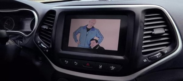
You verify the windshield wiper switch is in the OFF position. You switch it on and off a few times, but it has no effect. All of the sudden, the radio shuts off. An image of a skull and wrenches logo appears on the touchscreen. Rick Astley’s “Never Gonna Give You Up” begins blaring out of the speakers, and the four doors lock in perfect synchronization. The AC fans come on at max settings while at the same time, you feel the seat getting warmer as they too are set to max. The engine shuts off and the vehicle shifts into neutral. You hit the gas pedal, but nothing happens. Your brand new Jeep rolls to a halt on the side of the freeway, completely out of your control.
Sound like something out of a Hollywood movie? Think again.
[Charlie Miller], a security engineer for Twitter and [Chris Valasek], director for vehicle safety research at IOActive, were able to hack into a 2014 Jeep Cherokee via its wireless on-board entertainment system from their basement. A feature called UConnect, which allows the vehicle to connect to the internet via a cellular connection, has one of those things you might have heard of before – an IP address. Once the two hackers had this address, they had the ‘digital keys’ to the Jeep. From there, [Charlie] and [Chris] began to tinker with the various firmwares until they were able to gain access to the vehicle’s CAN bus. This gives them the ability to control many of the car’s functions, including (under the right conditions) the ability to kill the brakes and turn the steering wheel. You probably already have heard about the huge recall Chrysler issued in response to this vulnerability.
But up until this weekend we didn’t know exactly how it was done. [Charlie] and [Chris] documented their exploit in a 90 page white paper (PDF) and spoke at length during their DEF CON talk in Las Vegas. That video was just published last night and is embedded below. Take look and you’ll realize how much work they did to make all this happen. Pretty amazing.
Continue reading “How Those Hackers Took Complete Control Of That Jeep” →