Of course Maker Faire was loaded up with 3D printers, but we’re no longer in the era of a 3D printer in every single booth. Filament-based printers are passé, but that doesn’t mean there’s no new technology to demonstrate. This year, it was stereolithography and other resin-based printers. Here’s the roundup of each and every one displayed at the faire, and the reason it’s still not prime time for resin-based printers.
 Formlabs
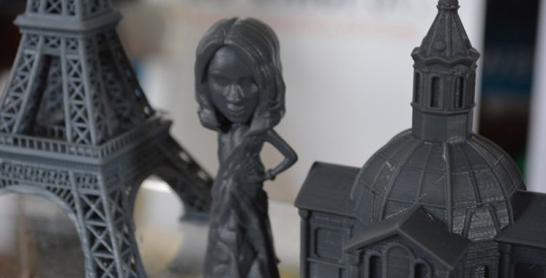
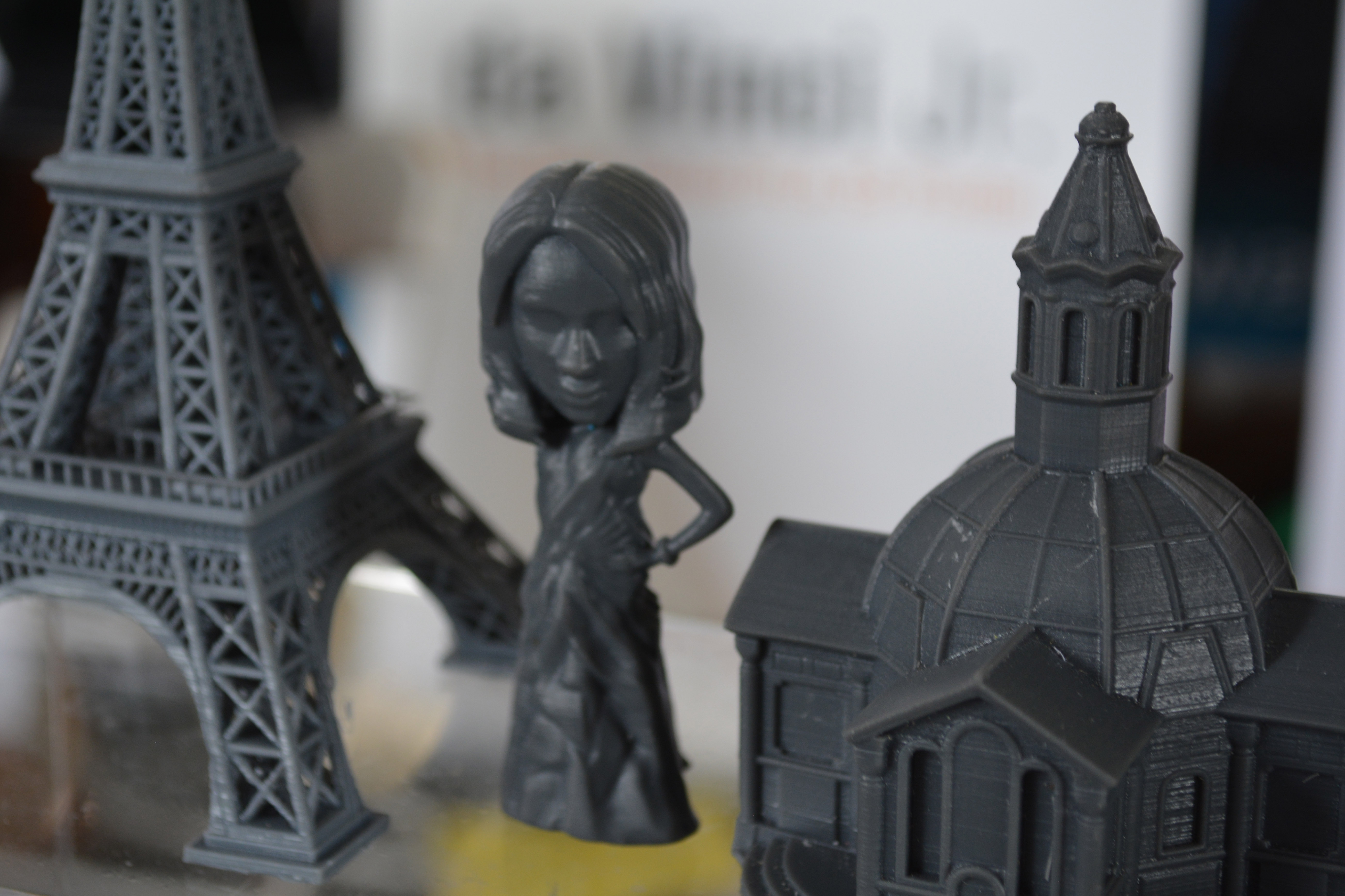
Of course the Formlabs Form 1+ was presented at the Bay Area Maker Faire. They were one of the first SLA printers on the market, and they’ve jumped through enough legal hoops to be able to call themselves the current kings of low-cost laser and resin printing. There were a few new companies and products at the Faire vying for the top spot, and this is where things get interesting.
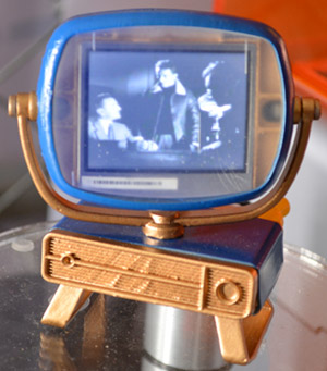
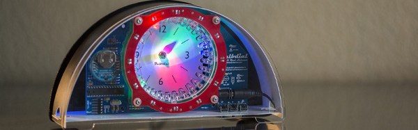
The folks at Formlabs displayed the only functional print of all the resin-based 3D printing companies – a tiny, tiny Philco Predicta stuffed with an LCD displaying composite video. The display is covered by a 3D printed lens/window. That’s the closest you’re going to get to an optically clear 3D printed part at the Faire.
XYZPrinting Nobel
XYZPrinting, the company famous for the $500 printer that follows the Gillette model: sell the printer cheap, sell expensive replacement filament cartridges, and laugh all the way to the bank. Resetting the DRM on the XYZPrinting Da Vinci printer is easy, the proprietary host software is done away with, and bricked devices are not. Time for a new market, huh?
Enter the XYZPrinting Nobel, a resin printer that uses lasers to solidify parts 25 microns at a time. The build volume is 125x125x200mm (5x5x7.9″), with an X and Y resolution of 300 microns. Everything prints out just as you would expect. As far as laser resin printers go, it’s incredibly cheap: $1500. It does, however, use XYZware, the proprietary toolchain forced upon Da Vinci users, although the Nobel is a stand-alone printer that can pull a .STL file from a USB drive and turn it into an object without a computer. There was no mention of how – or if – this printer is locked down.
DWS Lab XFAB
You’ve seen the cheapest, now check out the most expensive. It’s the DWS Lab XFAB, an enormous and impressive machine that has incredible resolution, a huge build area, and when you take into account other resin printers, a price approaching insanity.
First, the price: $5000 officially, although I heard rumors of $6500 around the 3D printing tent. No, it’s not for sale yet – they’re still in beta testing. Compare that to the Formlabs Form 1+ at $3300, or the XYZPrinting Nobel at $1500, and you would expect this printer to be incredible. You would be right.
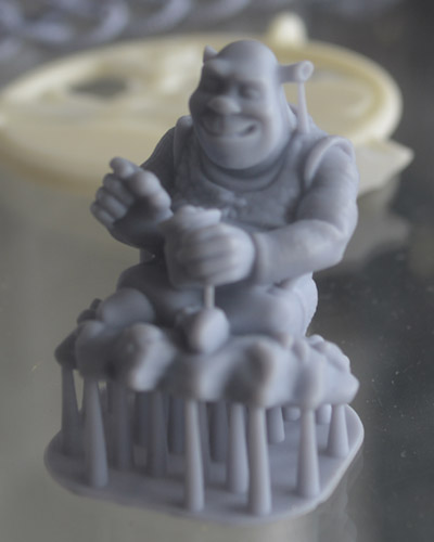
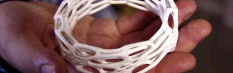
The minimum feature size of the XFAB is 80 microns, and can slice down to 10 microns. Compare that to the 300 micron feature size of the Form 1+ and Nobel, and even on paper, you can tell they really have something here. Looking at the sample prints, they do. These are simply the highest resolution 3D printed objects I’ve ever seen. The quality of the prints compares to the finest resin cast objects, machined plastic, or any other manufacturing process. If you’re looking for a printer for very, very high quality work, this is what you need.
Sharebot Voyager
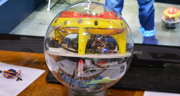
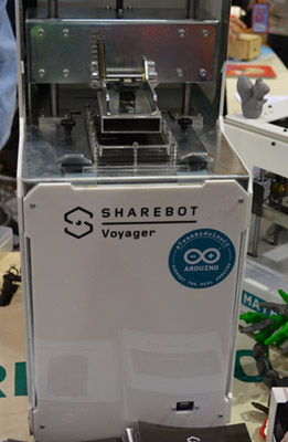 Also on display – but not in the 3D printing booth, for some reason – was the Sharebot Voyager. Unlike all the printers described above, this is a DLP printer; instead of lasers and galvos, the Voyager uses an off-the-shelf 3D DLP projector to harden layers of resin.
Strangely, the Sharebot Voyager was stuck in either the Atmel or the Arduino.cc (the [Massimo] one) booth. The printing area is a bit small – 56x96x100mm, but the resolution – on paper, mind you – goes beyond what the most expensive laser and galvo printers can manage: 50 microns in the X and Y axes, 20 to 100 microns in the Z. Compare that figure to the XFAB’s 80 micron minimum feature size, and you begin to see the genius of using a DLP projector.
The Sharebot Voyager is fully controllable over the web thanks to a 1.5GHz quad core, 1GB RAM computer that I believe is running 32 bit Windows. Yes, the spec sheet said OS: 32 bit Windows.
There were no sample prints, no price, and no expected release date. It is, for all intents and purposes, vaporware. I’ve seen it, I’ve taken pictures of it, but I’ve done that for a lot of products that never made it to market.
The Problem With Resin Printers
Taking a gander over all the resin-based 3D printers, you start to pick up on a few common themes. All the software is proprietary, and there is no open source solution for either moving galvos, lasers, or displaying images on a DLP projector correctly to run a resin-based machine. Yes, you heard it here first: it’s the first time in history Open Source hardware folk are ahead of the Open Source software folk. Honestly, open source resin printer hosts is something that should have been done years ago.
This will change in just a few months. A scary, tattooed little bird told me there will soon be an open source solution to printing in resin by the Detroit Maker Faire. Then, finally, the deluge of resin.
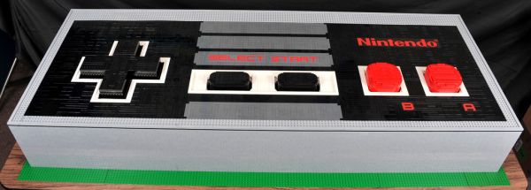
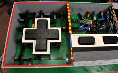 The four main sides of the controller case are standard stacked grey LEGO bricks. The inside of the case is mostly hollow, only with some supporting structures for the walls and buttons. The top is made from 4 individual LEGO panels that can be quickly and easily removed to access the interior components. The large LEGO buttons slide up and down inside a frame and are supported in the ‘up’ position care of some shock absorbers from a Technic Lego set. The shocks create a spring-loaded button that, when pressed down, makes contact with a momentary switch from Radio Shack. Each momentary switch is wired to a stock NES controller buried inside the large replica. The stock controller cord is then connected to an NES-to-USB adapter so the final product works with an NES Emulator on a PC.
 Last week’s prize was a


