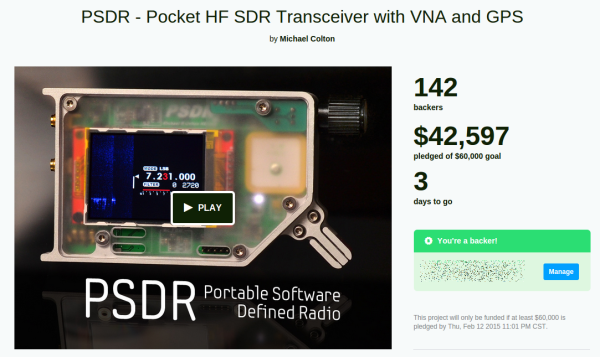
If you haven’t backed PortableSDR on Kickstarter, now’s the time to do it. [Michael Colton’s] project which frees a Software Defined Radio from being shackled to a computer is in the final three days and needs about $17,500 to make it.
We’d really like to see this one succeed, and not just because PortableSDR took 3rd place in the 2014 Hackaday Prize. Many a time we’ve heard people forecast the death of amateur radio (ham if you will). The ham community is special, it’s a great way to get mentorship in electronics, and deals in more than just digital circuitry. Plus, as [Greg] has pointed out, having a license and some know-how lets you build and operate really powerful stuff!
We see the PortableSDR as one way to renew interest in the hobby. We especially like it that you don’t need a license to operate the basic model — the transmitting circuits aren’t enabled when it arrives. This means you can learn about SDR, explore what’s going on over the airwaves, and only then take the leap by applying for your license and hack the unit to transmit. To be fair, the transmitter portion of the project hasn’t been published yet, which is about the only real concern we read in the Kickstarter comments. But we have faith that [Michael] will come through with that part of it. And if he needs help we’re sure he’ll have no problem finding it.
Now’s the time… let’s pull this one out in the final days!
Since just about everyone who would be interested in electronics has a decent cellphone now, there’s an idea that we don’t need USB or weird serial adapters anymore. Bluetooth LE is good enough for short-range communication, and there are a ton of boards and Kickstarter projects out there that are ready to fill the need.
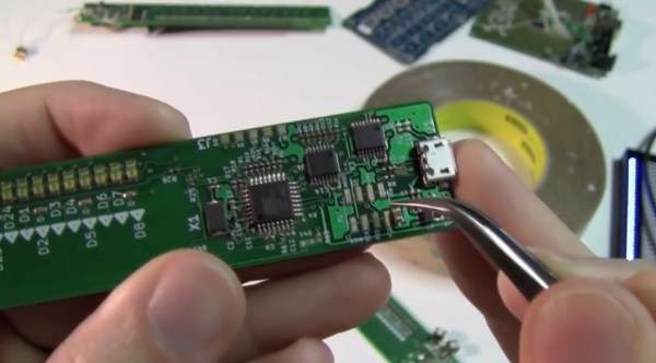
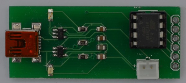
This board was developed as a means to connect sensors for a vintage motorcycle to an iOS device for display and data logging. A small, cheap board was needed that could be powered by a LiPo battery, and [Micah] created a board that fit his needs perfectly.
Four of the six IO pins on the ‘Tiny85 are broken out on a pin header; two are used to communicate with the BTLE module. It’s simple, fairly cheap, and can be powered by a battery. Exactly what you need if you want a wireless sensor board. All the files can be found in the Git repo and everything is open source. Not bad.
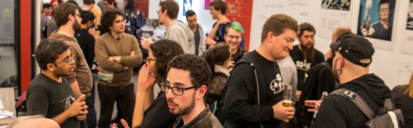
On Thursday night Hackaday hosted an event in San Francisco to commemorate the launch of the 2014 Hackaday Omnibus. Our first print edition, compiled to commemorate some of the finest original content which we published last year should begin shipping as early as today. To celebrate the occasion, we were graced by a full house of amazing guests. Is it lame to say some of the people I respect most in the world were there?
Lightning Talks
[David Grossman]
[Chris McCoy]
[Emile Petrone]
[Elecia White]
[Jonathan Foote]
[Priya Kuber]
[Sophi Kravitz]
[Mike Szczys]
Whenever you get a lot of people together, a good rule of thumb is to seize the opportunity to have them speak about what they’re doing. It’s not a big “ask” either; 8-minutes on what you’re passionate about is pretty simple.
[Jonathan Foote] gave a talk on generating RGBY colors from Hue. The project is ongoing but explores the concept of mixing colors of light with one additional source added to traditional red, green, and blue. [Priya Kuber] recently moved to San Francisco. She recently concluded more than a year of standing up the Arduino office in India (relevant but unrelated video). Her talk covered the emerging maker/hacker hardware scene in India which is showing amazing growth. [Chris McCoy] demonstrated his Raver Rings which began a Kickstarter on the same day. [Elecia White] of embedded.fm spoke about the educational opportunities that podcasts and other delivery medium provide and the responsibility we all have to guide our continued learning. [Emile Petrone] talked about an upcoming feature for his site Tindie which will add manufacturer information and ratings to the mix. And rounding things out [Dave Grossman] gave a talk on his Virtual Carl project which used video footage of his grandfather, combined with a Raspberry Pi and peripherals to create a remembrance of the man in virtual form.
Demos
[Ben Krasnow] shows off the chamber containing supercritical carbon dioxide.During the rest of the evening there were a few spectacular demos going on. First, [Ben Krasnow] who is well known for his Applied Science series (among a million other accolades), brought at least two demos with him. The first was a pressure chamber made out of two massively thick discs of acrylic separated by a metal ring. Inside the void he had pumped and pressurized CO2. When the chamber is heated it, the contents become Supercritical Carbon Dioxide and the visual transition between liquid and gas disappears.
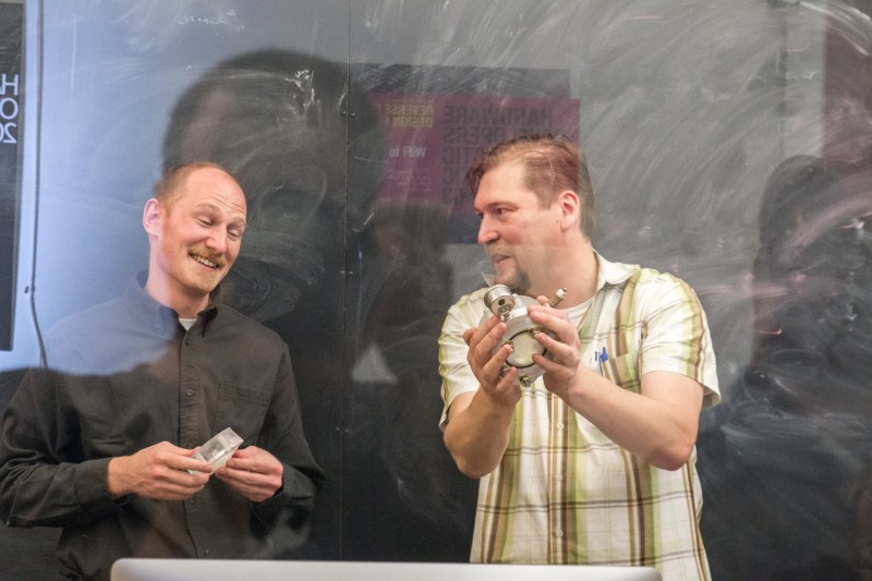
He also showed off a lens that can be focused electronically. This is not mechanical, there are zero moving parts. Instead a droplet of oil floating in water is the lens. A 75V, AC power supply pulls on the droplet, altering the meniscus to focus the lens. He didn’t fabricate the device from scratch, but the concept is completely new to us and quite interesting.
[Brian Benchoff] poses with Othermill hardwareOthermill is located in the SF area. They produce a desktop milling machine which is spectacular at routing PCBs. The little wonder isn’t limited to that though. Above you can see [Brian] holding up a milled wooden plaque which has milled mother-of-pearl inlays. The table is also strewn with other examples in wax, metal, wood, and more.
Cocktail Hour
The rest of the evening was devoted to conversation on all topics. Get enough hardware geeks in one room and they’ll solve the world’s problems, right? That’s a conversation for another post.
Couldn’t make it to this one but still in the San Francisco area at least occasionally? We held this at the Supplyframe office. They host a ton of great events like the Hardware Developers Didactic Galactic.
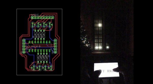
[Akhil Stanislavose] wanted to spice up his window decorations for the holidays. Inspired by blinkenlights, he decided to make his front window interactive. The Blinken Window is a grid of 6 x 10 programmable LEDs running on a Raspberry Pi. Since a RasPi doesn’t have enough GPIO pins for 60 LEDs, [Akhil] built an expander board using 8 daisy chained standard CD4094 (74HC595 could also be used) shift registers to accommodate them.
[Akhil] designed a PCB to replace the expander board for future use. It is modular in nature so that many of them can be connected together to provide as many outputs as one needs, allowing any size window to become a Blinken Window. The PCBs are still being fabricated, but the Eagle files are available for download (zip file). Ruby was used to implement the API. You can find the project files on GitHub, which also features a simulator that you can run on your computer to see how an animation or game will end up looking on the window. In the demo video, [Akhil] demonstrates how you can use the Blinken Window to play a version of Pong using your smartphone as the controller. [Akhil] has also provided a few basic animation examples that can be expanded upon. We’d enjoy seeing an implementation of Tetris. There’s so many fun ways to turn regular windows into dynamic displays, we’re starting to look scornfully at our own lazy, air leaking windows.
While many of us have made and documented our open source projects, not many of us have tried to sell our design to the masses. [Scott] developed, marketed, and “bootstrapped” a cool looking MIDI controller. Now, before you get your jumpers in a bunch – the project is completely open source. [Scott] documented the entire process of not only the design, but the trials and tribulations of bringing it to market as well. Calculating costs, FCC testing and the many other challenges of bringing a consumer electronics device to market are all detailed in his blog. Join me while we look at the highs and lows of his interesting and eventually worthwhile journey.
Putting yourself into a game where orders are in the tens of thousands, with hundreds of thousands of dollars changing hands is not easy when you’re just a guy with an idea and a soldering iron. [Scott] was up for the challenge, however. He quickly realized that much of the margin is spent on advertising and to cover risk. On his last order, some of the paint was chipping off. He had to fix the paint and repackage everything – all at his cost.
He also talks about the learning process of product design along the way. His original idea was to make a volume controller, but couldn’t sell a single one. He was forced to redesign the software into the MIDI controller as it exists today. He tried to launch a Kickstarter, but was rejected. This turned out to be a good thing, however, because he would have wound up kickstarting a product that didn’t work.
For advertising, he relied on Google and made some extremely detailed tutorials for his product. Many of them can be used for other MIDI controllers, and often come up in Google searches. Smart. Very smart.
Be sure to check out the video below, where [Scott] gets into some capacitive touch design theory, and talks about how not to cut your final product in half while on the CNC.
Have any of you ever tried to mass produce and sell one of your designs? Let us know in the comments!
Network Analyzers are frequently used for measuring filters, making them extremely valuable for building radios and general mucking about with RF. They are, however, extremely expensive. You can, however, build one in an Altoids tin with an Arduino Nano, a small screen, and an AD9850 frequency synthesis module picked up on eBay.
The basic idea behind a network analyzer is to feed a frequency into a device, and measure the amplitude coming out of the device, and plot this relationship over a frequency. [Bill Meara] has been a human network analyzer before, changing frequencies and plotting the output of devices under test by hand. [DuWayne] (KV4QB) build a device to automate the entire process.
The block diagram is easy enough – an AD9850 sends a signal to the device, and this is measured by the Arduino with a small amplifier. The signal is measured again when it comes back from the device under test, and all this is plotted on a small display. Simple, and [DuWayne] is getting some very good readings with a lowpass filter and crystal filter made on a small solderless breadboard.
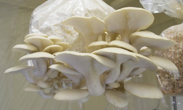
Lots of people have developed their own systems for automating the growth of plants. Keeping the environment under tight control leads to better yield, and computers are better than humans at remembering to water the plants regularly. [Kyle] is into growing mushrooms (the legal, edible type) and automating things. This led to his system for automated mushroom cultivation.
We’ve seen an automated system for growing fungi before, but [Kyle]’s project is a bit bigger. He’s built a sealed room for growing mushrooms. The room is sealed with a plastic sheet, using magnetic strips to create a doorway. Within the room, a heater, humidifier, and circulation fan control the environment. Temperature, humidity, and dew point in the chamber are constantly monitored and adjusted as necessary.
The entire system is controlled with a Raspberry Pi and custom software, which is available on Github. GNUPlot is used to generate graphs, which are accessible through a web server. The web interface also allows the parameters of the chamber to be tweaked remotely. Based on the settings, the Raspberry Pi controls a set of relays to keep the chamber in an ideal state.
![[David Grossman]](https://i0.wp.com/hackaday.com/wp-content/uploads/2015/02/mvi_4675-1.jpg?w=276&h=156&ssl=1 "MVI_4675-1")
![[Chris McCoy]](https://i0.wp.com/hackaday.com/wp-content/uploads/2015/02/img_4709.jpg?w=276&h=184&ssl=1 "IMG_4709")
![[Emile Petrone]](https://i0.wp.com/hackaday.com/wp-content/uploads/2015/02/img_4694.jpg?w=516&h=344&ssl=1 "IMG_4694")
![[Elecia White]](https://i0.wp.com/hackaday.com/wp-content/uploads/2015/02/img_4686.jpg?w=530&h=353&ssl=1 "IMG_4686")
![[Jonathan Foote]](https://i0.wp.com/hackaday.com/wp-content/uploads/2015/02/img_4665.jpg?w=262&h=175&ssl=1 "IMG_4665")
![[Priya Kuber]](https://i0.wp.com/hackaday.com/wp-content/uploads/2015/02/img_4652.jpg?w=262&h=174&ssl=1 "IMG_4652")
![[Sophi Kravitz]](https://i0.wp.com/hackaday.com/wp-content/uploads/2015/02/img_4634.jpg?w=396&h=264&ssl=1 "IMG_4634")
![[Mike Szczys]](https://i0.wp.com/hackaday.com/wp-content/uploads/2015/02/img_4600.jpg?w=396&h=264&ssl=1 "IMG_4600")
![[Brian Benchoff] poses with Othermill hardware](https://hackaday.com/wp-content/uploads/2015/02/img_4672.jpg?w=800)