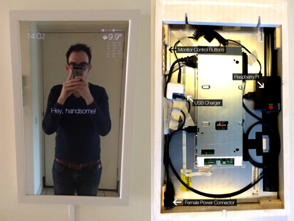
Who wouldn’t want a mirror that compliments them first thing in the morning? [Michael]’s Magic Mirror does this and more. [Michael] got the idea for his mirror during an epic Macy’s shopping trip with his girlfriend. While looking for a boyfriend chair, [Michael] noticed a mirror with a lighted sign behind it. Intrigued by the effect, [Michael] realized he could build it – and build it better!
Back at home [Michael] set to work. The Magic Mirror uses a piece of one-way mirror, similar to infinity mirrors. Instead of LED’s and another mirror, [Michael] wanted to embed an entire monitor behind the glass. In order to keep the mirror thin, [Michael] needed a monitor with cables exiting toward the side or bottom rather than directly out the back. He found what he was looking for in an Iiyama monitor. Yanking the case off a brand new LCD can be a bit nerve-wracking, but [Michael] pulled it off in pursuit of a thin final product.
Magic Mirror’s frame is built with standard 2×4 lumber. [Michael] had the foresight to include some cooling holes for the heat generated by the monitor. The heavy 6.5Kg final product required a double mounting point.
With a good-looking case, it was time to get some equally good-looking data to display. [Michael] used a Raspberry Pi to drive his display. He switched the Pi’s display mode to portrait and installed Chromium in kiosk mode. The entire mirror is essentially a web page. [Michael] used some simple HTML, CSS and Javascript to pull time and weather data down from various feeds. The page is rendered in a clean Helvetica Nueve Neue font with matching icons. A handsome build indeed!
 The SID chip inside the Commodore 64 and 128 is arguably still the gold standard for chip tunes, and the C64 itself still a decent computer for MIDI sequencing. [Frank Buss] realized most of the MIDI cartridges for the Commodore computers are either out of production or severely limited,
 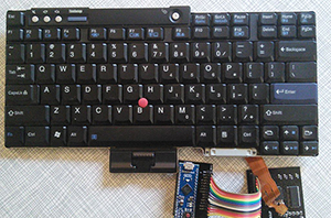 It doesn’t have buckling springs, Cherry blues, or even the wonderful if forgotten Alps switches, but the keyboard found in ThinkPads has the best keyboard action of any laptop around. They would make a great USB conversion keyboard, but the board to board connector is very hard to find, and no one has yet managed to get the keyboard and track point working as a USB HID device.