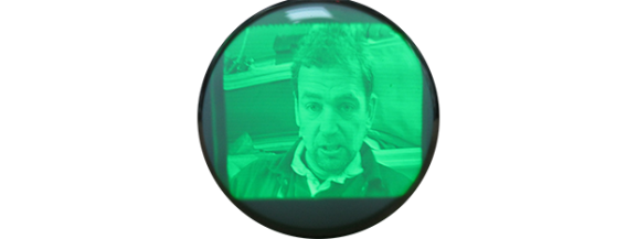
[GK] has a bit of a fetish for old oscilloscopes, and since he’s using an old ‘scope tube, the design was rather simple for him; there aren’t any schematics here, just what he could put together off the top of his head.
Still, some of [GK]’s earlier projects helped him along the way in turning this CRT into a monitor. The high voltage came from a variable output PSU he had originally designed for photomultiplier tubes. Since this is a monochrome display, the chrominance was discarded with an old Sony Y/C module found in a part drawer.
It’s a great piece of work that, in the words of someone we highly respect is, “worth more than a gazillion lame Hackaday posts where someone connected an Arduino to something, or left a breadboard in a supposedly “finished” project.” Love ya, [Mike].
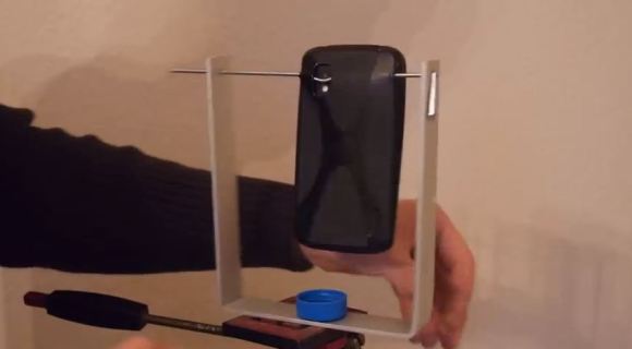
Android phones have a cool function called Photo Sphere — unfortunately, unless you’re very steady and can manipulate the phone around its camera’s axis… the results aren’t that amazing. Unless you make a cheap 360 degree panorama head for your tripod that is!
[Oliver Krohn] designed this super simple adapter which you can mount on any tripod. It’s a U-shaped bent piece of aluminum, a bottle cap with a 1/4-20 nut, a thick piece of wire, and a cellphone case. The wire is bent with a notch to sit just below the camera’s lens on the cellphone — it is also placed directly above the tripods panning axis. This puts the nodal point in the perfect place, which allows for a great photo sphere every time.
To see how it works (and the amazing results!) stick around for the following video.
If you do a survey of what makes and models of classic computers manage to pull off a Retro Success by loading our Web 1.0 retro site, you’ll notice a disproportionate number of classic Macintosh computers, the cute, small all-in-one boxes with a nine-inch black or white screen. Part of this is the nigh indestructible nature of these boxes, and part of this is the networking built into every classic Mac – AppleTalk.
The physical connections for AppleTalk is just a small breakout box with two Mini-DIN connectors (or RJ11 phone jacks for PhoneNet) attached to one of the serial ports on the Mac. This isn’t just a null modem connection, though. An AppleTalk network can support up to 32 nodes, file transfer, networked printers, and in later updates booting an Apple IIGS from a networked drive. Whenever you have a few classic Macs in one room, an AppleTalk network is bound to appear at some point, especially considering the limitations of an 800kB disk drive for sneakernetting and the fact the AppleTalk software is supplied with every version of the operating system.
[Chris] had an old dual disk Macintosh SE he had brought back from the dead, but his modern expectations of Internet On Every Computer meant this cute little compy was severely lacking. Yes, SCSI to Ethernet adapters exist, but they’re surprisingly expensive. Modems are right out because of landlines. How did he solve this problem? With AppleTalk, of course.
After picking up a pair of PhoneNet adapters, [Chris] plugged one into a PowerPC mac running OS 9. MacTCP, the Apple TCP/IP control panel for classic Mac operating systems, is able to encapsulate IP traffic into AppleTalk Packets. After turning the PowerPC mac into a router, [Chris] managed to get his all-in-one SE on the internet.
The only problem with this setup is the browser. NCSA Mosaic doesn’t have the ability to send traffic to a proxy server, but another classic Mac browser, MacWeb 2.0c does. This allowed him to load up our retro site using forgotten and long unsupported technologies.
If you have an old computer sitting around, try to load our retro site with it. Take a few pictures, and we’ll put it up in one of our Retro Roundups
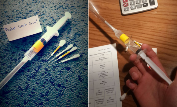
What can you do with needles, disposable syringes, superglue, cotton swabs, and scissors? If you answered ‘get hassled by TSA agents’, you’d be right, but you could also do what [Mski] did and make a pocket dart gun!
[Mski] used a 10mL syringe and a clear BiC pen body. He glued the pen barrel to the needle adapter on the syringe to make the chamber. He made the darts by cutting cotton swabs in half and inserting glue-covered needles. If you’ve never cut a cotton swab in half, they are hollow inside. What he has there are actually straight pins, which are cheaper than needles and come in larger quantities. The good news is you can make a bandolier of darts without breaking the bank.
Load your gun by shoving spitballs and/or darts up the chamber with a thin wooden stick, like a bamboo skewer. If you use your wife’s knitting needle, we recommend putting it back where you found it.
Do you prefer flaming projectiles and find clothespins easier to come by? Are you a hemophiliac or needle-phobic? Make this mini matchstick gun instead.
Atmel has just announced a new product line: SmartConnect. This moves beyond the point-to-point nature of WiFi Direct, and enables connections to standard access points. The SmartConnect series is designed for embedding in low cost devices that need to connect to a network.
The first devices in the SmartConnect line will be modules based on two chips: an Atmel SAMD21 Cortex-M0+ microcontroller and an Ozmo 3000 WiFi System on Chip. There’s also an on-board antenna and RF shielding can. It’s a drop in WiFi module, which is certified by the FCC. You can hook up your microcontroller to this device over SPI, and have a fully certified design that supports WiFi.
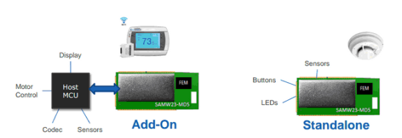
There’s two ways to use the module. The first is as an add-on, which is similar to existing modules. A host microcontroller communicates with the module over SPI and utilizes its command set. The second method uses the module as a standalone device, with application code running on the internal SAMD21 microcontroller. Atmel has said that the standalone option will only be available on a case to case basis, but we’re hoping this opens up to everyone. If the Arduino toolchain could target this microcontroller, it could be a great development platform for cheap WiFi devices.
The Add-On and Standalone Architectures
At first glance, this module looks very similar to other WiFi modules, including the CC3000 which we’ve discussed in the past. However there are some notable differences. One major feature is the built in support for TLS and HTTPS, which makes it easier to build devices with secure connections. This is critical when deploying devices that are connected over the internet.
Atmel is claiming improvements in power management as well. The module can run straight from a battery at 1.8 V to 3.3 V without external regulation, and has a deep sleep current of 5 nA. Obviously the operating power will be much higher, but this will greatly assist devices that sporadically connect to the internet. They also hinted at the pricing, saying the modules will come close to halving the current price of similar WiFi solutions. SmartConnect is targeting a launch date of June 15, so we hope to learn more this summer.
We’re always excited to see better connectivity solutions. If Atmel comes through with a device allowing for cheaper and more secure WiFi modules, it will be a great part for building Internet of Things devices. With a projected 50 billion IoT devices by 2020, we expect to see a lot of progress in this space from silicon companies trying to grab market share.
The folks at Physalia studio were asked by a company called IdN to produce a little bit of video with a logo. After tossing a few ideas around, they hit upon the concept of projecting the IdN logo inside a falling water droplet. CGI would never get this idea right, so the finished product is the result of stop-motion animation created inside several thousand falling drops of water.
Taking a picture of a falling water droplet was relatively easy; a small drip, a laser pointer and photodiode, and a flash trigger were all that was needed to freeze a drop of water in time. The impressive part of the build is a motion control system for the camera. This system moves the camera along the vertical axis very slowly, capturing one water droplet at a time.
Behind the droplet is a an animation that’s seemingly inspired by a Rorschach test, ending on the IdN logo. The frames for these animations were printed out and placed inside the test chamber/studio upside down to account for the optical effects of a sphere of water.
The end result is a product of over 20,000 pictures taken, all edited down into a single 30-second shot. An amazing amount of work for such a short video but as you can see in the videos below, it’s well worth the effort.
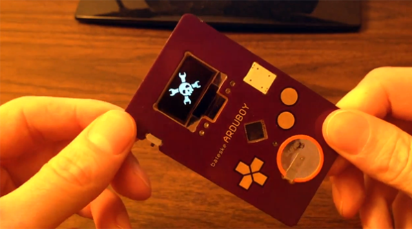
Think you’ve seen every possible type of Arduino based hand held video game? [Kevin] managed to coax something new out of the theme with a very clever credit card sized console that uses some very interesting construction techniques.
The inspiration for this project began when [Kevin] dropped an SMD resistor into a drill hole on a PCB. This resistor fell right through the hole, giving him the idea creating a PCB with milled cutouts made to fit SMD components. With a little experimentation, [Kevin] found he could fit a TQFP32 ATMega328p – the same microcontroller in the Arduino – in a custom square cutout. The rest of the components including a CR2016 battery and OLED display use the same trick.
The rest of the design involved taking Adafruit and Sparkfun breakout boards, and modifying the individual circuits until something broke. Then, off to Eagle to create a PCB.
[Kevin]’s experiment in extremely unusual PCB design worked, resulting in a credit-card sized “Game Boy” that’s only 1.6 millimeters thick. The controls are capacitive touch sensors and he already has an easter egg hidden in the code; enter the Konami code and the Hackaday logo pops up to the tune of [Rick Astley]’s magnum opus.
Now [Kevin] is in a bit of a bind. He’d like to take this prototype and turn it into a crowd sourced campaign. In our opinion, this “Game Boy in a wallet” would probably do well on a site like Tindie, but any sort of large scale manufacturing is going to be a rather large pain. If you have any wishes, advice, of complaints for [Kevin] he’s got a few links at the bottom of his project page.