20 MPH IKEA Poäng Chair With Aerospace-Inspired Control Panel

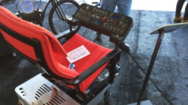
Spending time at work sitting on the same drab chair can get boring after a while, even if you’re lucky to use a comfortable recliner. If you want to win the Office Olympics, you need something with a bit of pep. [StuffAndyMakes] wanted to build a completely ridiculous motorized office chair. A couple of years in the making, and he’s ready to unleash the 20 MPH IKEA Poäng chair with aerospace-inspired control panel!

The OfficeChairiot MkII, as he has christened it aptly,  is a motorized IKEA Poäng comfy chair. It uses off-the-shelf scooter parts to roll around : Batteries, motors, chains, sprockets, tires, axles, and  bearings. The OfficeChairiot MkII is basically three main parts – the Chassis, the Control Panel and the comfy chair. One of the main parts of the chassis is the motor controller  – The Dimension Engineering Sabertooth 2×60 motor controller – which is also used in beefy battlebots. It’s capable of carrying 1,000 lbs. of cargo and can feed the drive system up to 60 amps per motor channel .

The brain on the chassis is an Arduino Mega which can be controlled via a hand held remote. The Mega also receives data from various sensors for motor temperature, power wire temperature, ambient air temperature, wheel RPM’s, Accelerometer’s, seat occupancy and GPS data. The firmware is designed to ensure safety. The hand held remote needs to ping the on-board Arduino twice a second. If it doesn’t hear from the Remote for whatever reason, the unit stops and turns off the lights.

The Control Panel is one crazy collection of switches, buttons, displays, a missile switch, a master key switch – in all over 30 switches and buttons. All of the devices on the panel are controlled via a second Arduino Mega, helped by a custom multiplexer board to help connect the large number of devices.

Here are a few more features the OfficeChairiot MkII boasts of :

  • 1.5 Horsepower from two 500W scooter motors
  • 20W stereo and MP3 sound effects
  • Weapons sounds, 15 different fart sounds, car alarm, horns, etc.
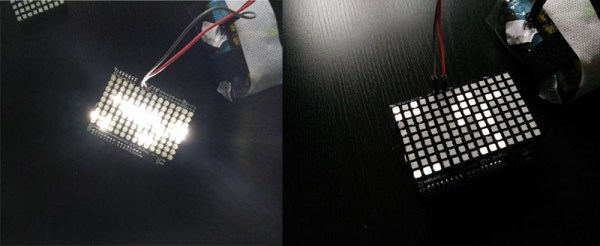
  • All LED lighting: Headlights, turn signals, 88 undercarriage RGB LEDs
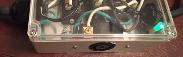
  • Plenty of homemade PCB’s
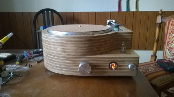
  • Custom built aluminum body panels (with help from Local Motors, the people behind the 3D printed car)

Aside from the handcrafted wood chassis and circuits boards and firmware, it’s all off-the-shelf stuff. [StuffAndyMakes] plans on open-sourcing the schematics, C++ code and CAD drawings – so post some comments below to motivate him to do so soon. We’d sure like to see a few more of these being built, so that Office Chair racing becomes a competitive sport. Check out the video after the break.

Continue reading “20 MPH IKEA Poäng Chair With Aerospace-Inspired Control Panel”

Portable 120V To 240V Converter; Or How To Fast Charge At Your In-Law’s House

[Nick Sayer] falls into the “would rather build it than buy it” category. This particular project is a clone of a fast electric vehicle charger. There are commercially available versions sold under the Quick 220 brand name. The idea is that for fast charging, some electric vehicles call for a 240V outlet and Americans without electric cars often don’t have one. If they do it’s for an appliance like a stove or clothes dryer and probably not found in the garage.

The device uses two hot and one ground to supply the 240V output which is, in some business where there is three phase power this will be closer to 208V but should still work. Obviously you shouldn’t be doing this unless you know exactly how it works, and we applaud [Nick] for airing these hazards while at the same time supplying the knowledge behind the concerns.

Two inputs for the beefy converter are supplied from outlets not just on separate circuits, but on two circuits whose hot lines are 180 degrees out of phase. That means identifying where there are two plugs, not protected by GFCI outlets or breakers, which are on two separate hot lines of split phase power. To protect the user, [Nick] designed in a set of relays which kill the circuit when one of the two supplies is unplugged. A system that didn’t have these protections would have mains voltage on the prongs of the disconnected plug.

We’ve seen very few car charging hacks. If you know of one, or have been working on your own, let us know!

DIY Turntable In A Beautiful Wooden Case

Old timers who have been around for the last 40 years or so have been fortunate enough to have lived through several audio reproduction technologies – Vinyl Records, Cassette Tapes, Laser Disks and CD-ROM’s. Most will also swear that analog, especially vinyl records, sounded the best. And when it comes to amplifiers, nothing comes close to the richness of vacuum tubes.

[MCumic10] had a long time desire to build his own HiFi turntable encased in a nice wooden housing, with the electronics embedded inside. When he chanced upon an old and battered turntable whose mechanism barely worked, he decided to plunge right in to his pet project. The result, at the end of many long months of painstaking work, is a stunning, beautiful, wooden turntable. Especially since in his own words, “I didn’t have any experience in electronics or woodworking before I started this project so it took me many long months in learning analyzing and frustration. I burned some electronic parts few times and made them from the beginning.”

The build is a mix of some off the shelf modules that he bought off eBay and other sources, and some other modules that he built himself. He’s divided the build in to several bite sized chunks to make it easy to follow. The interesting parts are the 6N3 Valve Preamplifier (the main amplifier is solid-state), the motorized Remote Volume Control Input kit, and the Nixie tube channel indicator. And of course the layered, plywood casing. By his own reckoning, this was the toughest and longest part of his build, requiring a fairly large amount of elbow grease to get it finished. He hasn’t yet measured how much it tips the scales, but it sure looks very heavy. The end result is quite nice, especially for someone who didn’t have much experience building such stuff.

Thanks [irish] for sending in this tip.

PortableSDR Needs A Cinderella Story To Finish Its Kickstarter

If you haven’t backed PortableSDR on Kickstarter, now’s the time to do it. [Michael Colton’s] project which frees a Software Defined Radio from being shackled to a computer is in the final three days and needs about $17,500 to make it.

We’d really like to see this one succeed, and not just because PortableSDR took 3rd place in the 2014 Hackaday Prize. Many a time we’ve heard people forecast the death of amateur radio (ham if you will). The ham community is special, it’s a great way to get mentorship in electronics, and deals in more than just digital circuitry. Plus, as [Greg] has pointed out, having a license and some know-how lets you build and operate really powerful stuff!

We see the PortableSDR as one way to renew interest in the hobby. We especially like it that you don’t need a license to operate the basic model — the transmitting circuits aren’t enabled when it arrives. This means you can learn about SDR, explore what’s going on over the airwaves, and only then take the leap by applying for your license and hack the unit to transmit. To be fair, the transmitter portion of the project hasn’t been published yet, which is about the only real concern we read in the Kickstarter comments. But we have faith that [Michael] will come through with that part of it. And if he needs help we’re sure he’ll have no problem finding it.

Now’s the time… let’s pull this one out in the final days!

Mini Autonomous Robot

Cute Tiny Robot Gets A Pair Of Hacked Eyes

One day while at our poor, poor Radio Shack, [davidhend] purchased a little 6-legged walking robot. It came with an infrared remote that allowed a user to control its movements from afar. After a few minutes of making the robot walk around [davidhend] got bored and decided it would be a great toy to hack.

His plan was to make the robot autonomous and able to avoid obstacles. To start off, the robot was taken apart enough to expose the circuit board. There he found a ST1155A bi-directional motor driver that was controlled by an on-board microcontroller. After checking out the ST1155A data sheet, [davidhend] thought he would be able to drive it with an Arduino. So, out came the soldering iron and all the unnecessary components were removed from the original circuit board.

An off the shelf PING))) sensor was mounted on the front of the robot and is responsible for detecting obstacles. That information is then sent back to the Arduino Nano which controls the motor driver to make the robot back up, turn and then start walking straight again until another obstacle is detected. [davidhend] made his Arduino Code (.zip file) available to anyone who wants to make a similar project. Check out the video after the break!

Oh, and if you plan to run down to the Shack to pick up a robot of your own you better do it like right now.

Continue reading “Cute Tiny Robot Gets A Pair Of Hacked Eyes”

LVBots CES Open House: Tabletop Challenge And Clothes Bot

LVBots, a club for robot building enthusiasts in Las Vegas, held an open house the week of CES. This was the only trip [Sophi] and I took away from the conference halls of The Strip and it was a blast! The group holds meetings twice a month in a space provided by Pololu — a well-known robotics and electronics manufacturer headquartered just south of McCarran International Airport.

Before the formal part of the gathering started there were several builds being shown off. [Claire] and [Brian] recently participated in an AT&T sponsored hackathon. Their creation is a robotic closet. The system involves moving racks of clothing which are tracked by a smartphone app. Interesting features discussed for the software include monitoring when each garment was last worn, last washed, and if it is appropriate for current weather conditions. Dig into the code in their repo.

In other parts of the room a pair of line-following robots did their thing, and a couple of sumo-bots competed to push each other out of the ring. A large group was gathered around the projector watching videos of robots of all types, brainstorming about the difficult parts, how they were overcome, and how these methods may be applied to their own build. I can attest that hanging with a group of people who are trying to cue up the most amazing robot demonstrations makes for amazing viewing!

As the organized part of the meeting began I was delighted to hear about a standing challenge from the LVbots group. The Tabletop challenge has multiple phases that serve to encourage builders to start modestly and then iterate to achieve new goals:

Phase 0: bring a robot to LVBots
Phase 1: travel back and forth without falling off
Phase 2: find an object and push it off
Phase 3: push object into a goal

[Nathan Bryant] was one of the two robot builders trying out the challenge on this night. He built this hexapod from balsa wood and three servo motors and was testing Phase 1. The bot includes a sensor dangling out in front of the robot to detect then the table surface is no long below. At that point it backs up a few steps, turns in place, and proceeds in the opposite direction. [Nathan] mentions that he worked out all the movements in a spreadsheet and that future firmware upgrades will dramatically increase the speed at which the bot moves. We love the audible cadence of the bot which is easily observed in the video above. At one point a leg dangles over the edge and it looks like [Nathan] pushed the bot back but I don’t remember him actually touching it so I’m calling this a trick of camera angle.

One phase further in the Tabletop Challenge is [Joe Carson]. He exhibited a wheeled robot he’s been working on that includes a gripper arm on the front. The robot looks around the table for a predefined color, in this case provided by a highlighting marker. When found the bot approaches, grips, and then proceeds to move the marker over the void where it is dropped out of existence; at least from the robot’s point of view.

3D Printable LED Diffusors

While you can get an LED matrix in any size or shape, the really cool looking ones that are perfect for low-res displays all have diffusors. When they come from a nameless Chinese factory, these diffusors are thin sheets of plastic set into an extruded plastic frame. Since [Jana] has a 3D printer, she figured a custom diffusor was just a few bits of filament and a SCAD file away.

The basis for this custom LED diffusor was a LoL Shield given to [Jana] by the creator at the recent 31C3 conference. This shield is really only just 126 LEDs, multiplexed and in an Arduino form factor, and that many LEDs were just too bright and indistinct next to each other. The plan for a 3D printed diffusor was hatched.

After taking a few measurements, a pair of OpenSCAD files were whipped up and printed out. Assembly consisted of pressing 126 tiny little white diffusors into a frame, but once everything was attached to the matrix, the results were worth it.

Check out the video below for the before and after, demonstrating what a few bits of plastic can do to a LED matrix.

Continue reading “3D Printable LED Diffusors”