The Cheapest And Easiest 3D Printer We’ve Seen So Far

3D printers are awesome, but boy are they frustrating. If you’ve built a RepRap Mendel, Prusa or Huxely, you know there’s nothing quite like trying to get a washer off of a threaded rod without disassembling the entire machine. This frustration in part sourcing, assembling and correctly aligning a printer is where printers like the Makerbot find their niche. There’s a new printer on the block that promises a 45 minute assembly time and less than 2 hours from starting the build to first print. It will do all this for under $500, electronics and motors included.

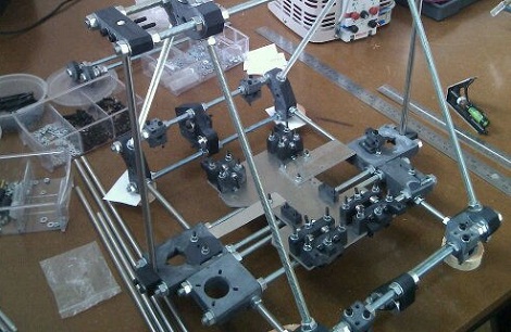
From the Flickr photoset, we can see that the Printrbot has 2 motors for the z-axis, uses sanguinololu electronics, and uses a derivative of Wade’s extruder – all proven design choices. Unlike the RepRaps, most of the frame is actually printed, and not built out of threaded rods. This drastically reduces the assembly and calibration time.

The inventor of the Printrbot, [Brook Drumm], has a Kickstarter up where he’s selling complete kits (electronics, motors and vitamins) for $499. This beats the very inexpensive SUMPOD in affordability. We haven’t been able to find the 3D design files for the Printrbot (although you can buy these printed parts for $75), and there’s no word on the build volume of the stock printer. That being said, the printrbot does have pretty good resolution. Check out the video of a Printrbot in action after the break.

Continue reading “The Cheapest And Easiest 3D Printer We’ve Seen So Far”

A Technique To Avoid Warping On Large 3D Prints

[Jamie Mantzel] figured out his own way of 3D printing large objects without fear of warping. First a bit of background information. When using a 3D extrusion printer like the RepRap or Makerbot, prints that span a large area tend to warp. That’s because these printers lay down one thin layer of plastic at a time. If the first layer cools too much, it will shrink a bit before the next layer is laid down. As that second layer cools it pulls the part toward the center, eventually bowing the part which causes it to hit the extruder head.

After having several prints encounter this issue [Jamie] decided to alter his design so that it wouldn’t cause these stresses. The first thing that he did was to add alternating voids to a layer between the raft and the actual part. You can see these as notches on the bottom the piece pictured above. This takes care of the initial stresses from the first layer. Next, he adds holes wherever he can in the main body of the part. This is especially important on the edges of the piece where the warping forces will be the greatest.

He also moved the starting position of the bed closer to the extruder head. His hope is that this will help the raft bond better, and resist pulling away from the bed during printing.

See his video explanation of his adventure after the break.

Continue reading “A Technique To Avoid Warping On Large 3D Prints”

Halloween Hacks: Arc Reactor Costume

Halloween is the time of year where you can dress up as a pirate, muppet, or superhero and no one will bat an eye. During this holiday of expanded social permissiveness, [Nbitwonder] decided that building an Arc Reactor from Iron Man would be appreciated by his engineering cohort.

The ‘body’ of the reactor was manufactured on the RepRap Mendel we covered from beginning to end. A few minutes with Google Sketchup was all that was needed to generate the files and send them to the printer. In a few short hours, [Nbitwonder] had the body of his Arc Reactor.

The board design was thrown together in Eagle and etched. 11 blue SMD LEDs were thrown into the mix along with some borrowed resistors. Pieces of a hard drive spindle and a little bit of wire rounded out the parts list, and everything was assembled with the DIYers favorite tool, the hot glue gun. Not a bad job for a few hours of work.

The files for the Arc Reactor are up on Thingiverse along with a Flickr photoset.

Pololu Compatible Relay Driver

[Bart] built a couple dozen Pololu compatible relay drivers.

If you have a Reprap, you’re probably familiar with the Pololu stepper motor driver. These tiny pieces of kit provide stepper motor control for Gen 6, RAMPS, or Sanguinololu Reprap electronics. There’s a small problem with all these boards, though; there’s no way to control any high-power devices from these boards except for stepper motors. Controlling a spindle for a home-built CNC router would be great, but apart from attaching a Dremel to your x-axis, you’re just about out of luck.

[Bart]’s relay driver takes the step and direction inputs from the stock Pololu stepper driver and connects each of those to a MOSFET. From there, a relay can be hooked up to the driver to control the spindle for a router, or a whole bunch of fans for a homebrew laser cutter.

The schematic and Gerber files are up on [Bart]’s webzone. The part count is very low, and the entire board could easily be built on a piece of perfboard. Check out the demo on the other side of the jump.

Continue reading “Pololu Compatible Relay Driver”

An Interview With Bre Pettis, Founder Of MakerBot Industries

For those of you that don’t know, the Makerbot is a 3D printer created by Bre Pettis. It is probably the best-known 3D printer that you can buy at a price point meant for the hobbyist. Although this article doesn’t go into how the MakerBot is made, it focuses instead about the business itself and the man behind it. Bre was a hobbyist maker just like many of our readers, but decided to turn his passion into a successful business.

Although not all businesses are a success, Bre has made quite a start at becoming one. His company now employs 50 people and is currently hiring (like this posting for a “Web Warrior”) and has just secured $10 million in venture capital funding! Check out the full interview for all the details. It may inspire others to go from “hobby maker” to “professional.”

For other 3D printing-related posts, check out this one about the RepRap printer which is capable of replicating itself. For other ways to make your own parts, this rotomold machine may be of interest or this semi-DIY CNC router.

They May Be For Developing Countries, But We Want A Concrete Lathe

At the 2009 Ghana Maker Faire, [Pat Delany] met a young carpentry student that saved for three months to buy a cheap Chinese wood plane. He was confounded by this distribution of resources, so [Pat] created the Concrete Lathe project that aims to get useful machine tools out to where they’re needed most.

The idea for concrete machine tools came out of the US involvement in World War I. America had been staunchly isolationist before committing to the war, and production of arms did not match the needed output. A man named L.I. Yeomans came up with the idea of building concrete lathes to produce artillery shells for the war effort.

Of course, the concrete lathe project is a bit more peaceful in its intentions. The concrete lathe is meant to be a cheap machine tool for developing nations. Both the concrete lathe and the Multimachine are meant to be built cheaply using scrap materials, reduce training time for machinists, and create other machine tools in a Reprap-like biological distribution.

There’s a ton of documentation on the concrete lathe wiki like the bed instructions torn from the pages of Ikea instructions, and the thread follower. While they’re still a lot of work and testing to be done, giving some manufacturing capability to those who need it most is a pretty noble cause.

Thanks [Rob] for sending this one in.

Improvised Metal Lathe

[McKGyver] needed a few parts manufactured. Instead of going the normal route – finding friends with machine tools or paying a machine shop, he improvised a rudimentary metal lathe.

As much as we love 3D printers, they’re not the be-all, end-all solution for everything. Sometimes, you need to get a little dirty and do it the old-fashioned way. [McKGyver] needed a way to produce aluminum shaft couplers to join stepper motors to lead screws. A 1940s grinding wheel was used for the headstock. Since [McKGyver] only needed couplers of one size, he made a jig out of wood to attach the aluminum blanks to the spindle. A drill and a focuser from a photographic enlarger makes up the tailstock of the improvised lathe. The use of a camera focuser is pretty clever. Unless the equipment has been damaged, it’s guaranteed to move in a straight line. A small laser was used to align the drill.

The finished couplers were concentric to 0.005″. A ‘passable precision’ for his application, and a clever build that doesn’t involve moving a thousand pound South Bend lathe.