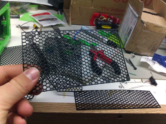
If you need a way to make openings in your project enclosures look nice just head on over to the 3D printer. In the image above [Alfred] is showing off the result of his Slic3r hack for printing mesh grills.
It’s important to note that you need to make sure you’re using Slic3r version 0.9.8. This won’t work with newer versions because starting with 0.9.9 the software will add a raft to the bottom of your design.
The grill can be in any shape you desire. It starts by modelling this outline, then extruding the edges downward the same distance as your desired mesh thickness. After importing the design file into Slic3r [Alfred] uses the support material settings to choose this honeycomb design. He then sets the fill density to zero. This means the design will not be printed at all, only the fill material, resulting in these honeycomb screens.
Slic3r’s a fantastic piece of software. Check out this interview with Slic3r’s lead developer.
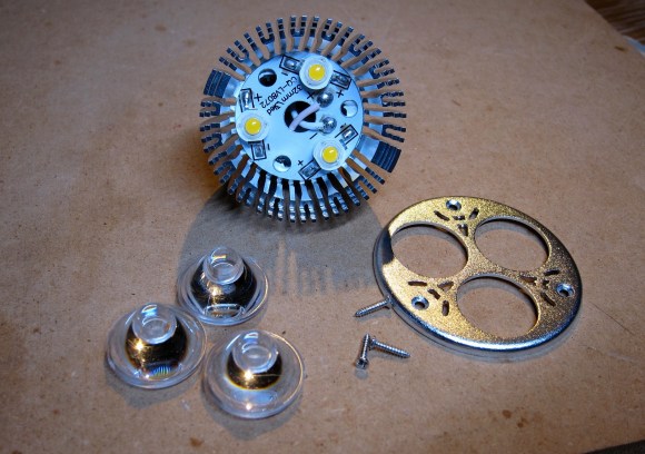 Halogen bulbs put out a lot of focused light but they do it at the expense of burning up a lot of Watts and generating a lot of heat. The cost for an LED replacement like the one seen disassembled above has come down quite a bit. This drove [Jonathan Foote] to purchase several units and he just couldn’t resist tearing them apart to try out a couple of hacks.


