Linux Picture Frame Serves As Wireless Raspberry Pi Display

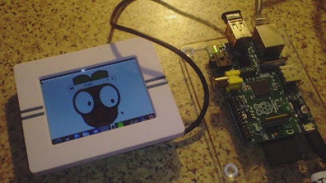
Here’s a novel approach to adding a display to your Raspberry Pi. Instead of using a wired display — either via the HDMI (which can feed a DVI port with a simple hardware adapter) or the composite video out — [Chris Bryden] decided to use Bluetooth to provide a wireless display. This really depends on the hardware that you have available. He snapped up a hackable digital picture frame for a song and used the 320×240 display for this project.

You can see the USB nub plugged into the RPi in the image above. It’s a Bluetooth dongle and there’s with a matching one on the digital frame. With the two networked in such a way [Chris] got to work setting up a VNC that would let him pull up the X desktop over the network.

This ends up being one of the best uses we’ve seen for the Bluetooth protocol, and the small screen offers a huge advantage over the use of a simple character display.

Building A CMOS Clock On A Breadboard

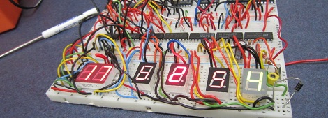
If you’re going to learn digital logic, why not aim high? That’s what [Easton] and his friend did when they built a clock using only 4000-series logic chips. On a breadboard, no less.

For a 1 Hz clock, [Easton] and his friend used a 4060 counter paired with a flip flop. This counts off 59 seconds until, with the help of an AND gate, the seconds counter rolls over to zero. After repeating that again for the minutes and building a similar circuit for the hour, and [Easton] had a working 4000-series 24-hour clock.

The breadboard clock may not be the prettiest thing, or a textbook example of how to prototype circuits,  but that was fixed with [Easton]’s friend’s PCB layout of a 12-hour clock. We couldn’t find any pics of this, but we’re sure it’s awesome and a great way to learn about logic and design.

An Interview With Laen (the Force Behind Dorkbot PDX)

[PT] recently interviewed [Laen], the man who makes it cheap and easy for hobbiests to have small PCBs manufactured. He created Dorkbot PDX’s PCB group order, a rapid turn PCB service which we see used in projects all the time (pretty much any purple PCB has gone through [Laen]).

Turns out his real name is [James Neal]. He’s a sysadmin by trade but deals in recreational circuitry at night. We were surprised to learn that the service has been rebranded. Its new name is OSH Park and it’s got a purple website with a new submission system. In the interview he discusses the genesis of the service. Inspired by a group parts order (that’s a mouthful!) with other hackers in Portland he saw a need for boards on which to mount them. The service has grown so much that he was spending 2-4 hours per night panelizing the designs. He made the wise choice to include an automated submission service in the new website that takes care of most of this work for him.

The rest of the interview spans a large range of topics. [Laen] shares his feelings on getting the boards manufactured domestically. He speaks briefly on the future of the service, and riffs on why open source hardware has value to him.

Quadrotor Opera Begs For Lasers And Pink Floyd

In case quadrocopters aren’t cool enough, here’s an orchestrated quadrotor light show that was shown at the Cannes Lions International Festival of Creativity this last week. With 16 quadrotors and a few can lights, it’s a light show not to be missed.

This quadrotor show was created by a collaboration between KMel robotics and Marshmallow Laser Feast. The guys behind KMel are the same brilliant minds behind this nanocopter swarm that can play the [James Bond] theme. For this light show, the guys at KMel Robotics used a Vicon motion capture system to coordinate the flock of quadrotors, as seen in this picture.

With a servo-controlled mirror on the bottom of each quatrotor, each vehicle in the fleet is able to reflect beams of light around the stage and into the audience. Now it’s only a matter of time until a setup like this is used for a showing of Laser Floyd.

Tip ‘o the hat to [cesar] for sending this one in. Via IEEE Spectrum.

Edit: They’re not can lights. After watching in 1080p, [Impulse405] is pretty confident they’re High End studio spots or a wash with a tight focus. Thanks for keeping us honest, [Impulse405]!

Resurrecting A PS3 Controller That Won’t Charge

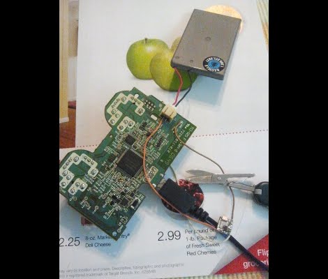
[SJM4306] grabbed a used PlayStation 3 from a game store that was going out of business. He got a pretty good deal on what had obviously been the floor model for a number of years. The one real problem was the controller that came with it. The thing was so filthy that he literally used gloves to disassemble and sanitize it. It worked just fine after that,until he discovered that it wouldn’t charge from the USB port as it’s supposed to. But he managed to replace the charging circuitry with some of his own.

When cleaning the insides of the controller he found there were numerous deposits of sludge which he attributes to spilled soda. This must have damage one of the chips responsible for charging because he was probing an unstable 2V rather than the regulated 5V which should be coming in on the USB lines. His solution was to desolder the USB port in order to separate its 5V pin from the PCB. He then etched a tiny board to host a MAX1555 charging IC. With the new hardware in place the controller is back in action.

Using An HD44780 Character LCD With The Raspberry Pi

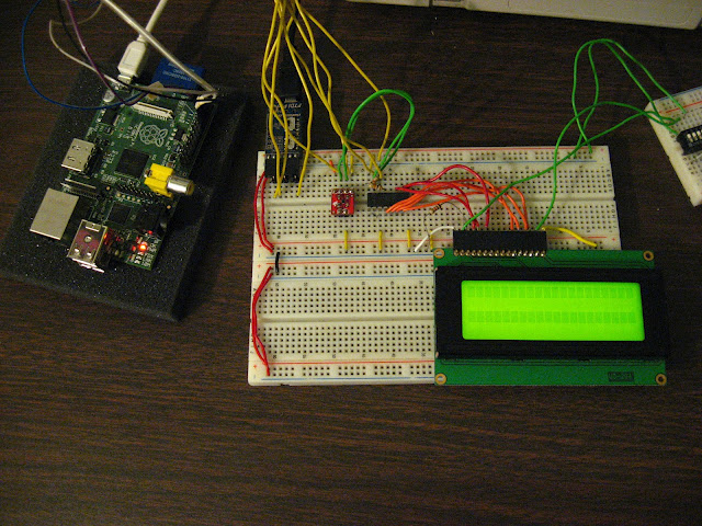
[Tech2077] is one of the lucky ones who already got his hands on a Raspberry Pi. He’s been looking into different interface options with the GPIO header and just posted a guide to using an HD44780 character display with the RPi. We like this approach because instead of doing some hard-core LCD work he’s using prototyping equipment you probably already have on hand.

Getting a character LCD running should be really simple. The gotcha is the logic level gap between the devices. If you’ve been working with Arduino, your add-ons are probably meant for a 5V power rail  and logic levels. The RPi outputs 3.3V logic. You could use a level converter (you’d need at least 7 pins to be converted in this case) or you can be a bit more clever. [Tech2077] grabbed an I2C port expander that uses just 2 of the RPi lines to address even lines of the display (four data bits plus three control bits). This is a bit of a hack, as the 3.3V logic is 0.2V below the recommended minimum for a digital 1 on the port expander. But it seems to work just fine! If it didn’t, a couple of NPN transistors would do the trick as well.

Addressing the new peripheral is just a matter of loading the i2c module and writing some Python.

Building A Pick And Place With 3D Printed Parts

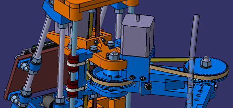
For the last few months, [HeliumFrog] has been building a SCARA bot to serve as the basis for a pick and place machine. Somewhat amazingly, this is the first robot of its kind to be printed on a 3D printer.

A SCARA-type robot is an articulated arm perfectly suited for transferring components from tubes and reels to a PCB. [HeliumFrog] began his build with an arm with large gears in joints driven by stepper motors and toothed belts. The Z axis was originally driven with a lead screw, but after a thoughtful redesign that was changed over to another toothed belt.

We’ve seen our share of DIY pick and place machines, but most of those have been based on a traditional X/Y Cartesian frame. [HeliumFrog]’s SCARA bot should be – theoretically, at least – faster and more accurate while taking up a smaller footprint in the workshop.

[HeliumFrog] is more or less done with the basics of his build, and is now moving on to building a plastic extrusion tool head for his SCARA bot. Very cool, and should make this robot capable of self-reproduction for under £400 (~$600).

You can check out a video of this articulated arm bot after the break.

Thanks, [Kyle] for sending this one in.

Continue reading “Building A Pick And Place With 3D Printed Parts” →