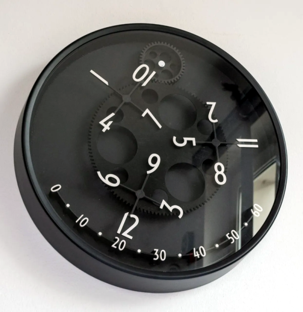
We always enjoy unique clocks, and a recent 3D print from [David Kingsman] caught our eye. It converts an Ikea clock into a very unusual-looking “wandering hour” clock that uses a Geneva drive to show a very dynamic view of the current time. The concept is based on an earlier wandering clock, but [David] utilized a different mechanism.
To read the clock, you note which hour numeral is in range of the “minute arc” and read the time directly. So if the 12 hour is over the 20-minute mark, the time is 12:20. Besides the clock, you need a fair number of printed parts, although they all look like relatively simple prints. You’ll also need 13 bearings and some metric hardware. A piece of cardboard used for the face rounds out the build.
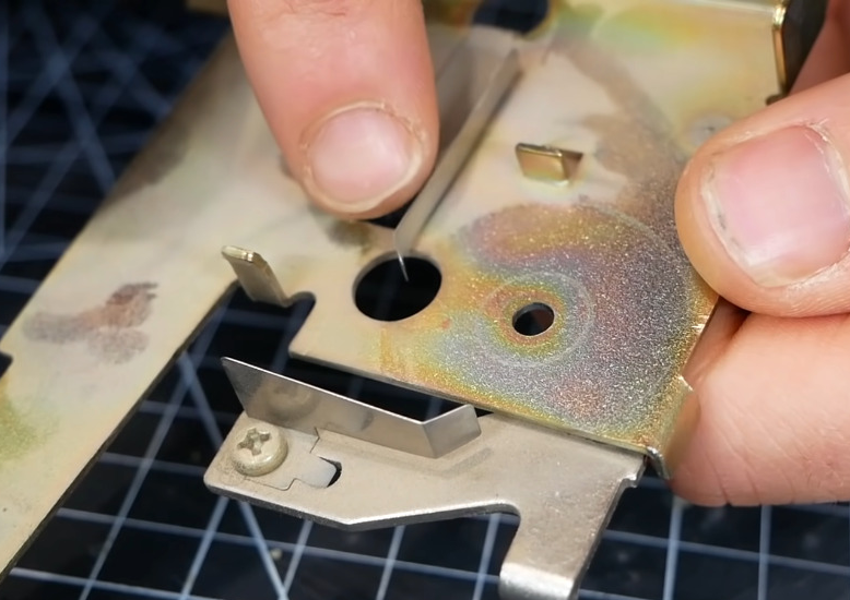
Modifying the clock is more than just taking it apart. There is a template file to print, and you’ll need to align it and drill holes as indicated.
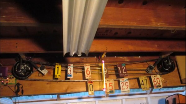
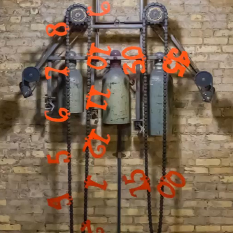
If you haven’t seen a Geneva drive before, it translates a continuous rotation into intermittent rotation. This isn’t the first clock we’ve seen use this kind of drive, although the last one we saw represented time differently. If you want something even more mechanical, try a chain-driven clock.