Reverse Engineering A Wireless Protocol

logic

Like all good tinkerers, [Andrew] decided to figure out how his wireless security system worked. Yes, it’s an exercise in reverse engineering, and one of the best we’ve seen to date.

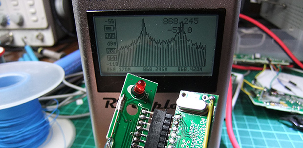
After breaking out the handheld spectrum analyzer and TV tuner SDR, [Andrew] cracked open a few devices and had a gander at the circuit boards. The keypad, PIR sensor, and base station all used a TI radio chip – the CC11xx series – that uses SPI to communicate with a microcontroller.

Attaching a logic analyzer directly to the radio chip and reading the bits directly, [Andrew] started getting some very good, if hard to understand data. From the security system specs, he knew it used a ’20-bit code’, but the packets he was reading off the SPI bus were 48 bits long. The part of this code was probably the system’s address, but how exactly does the system read its sensors?

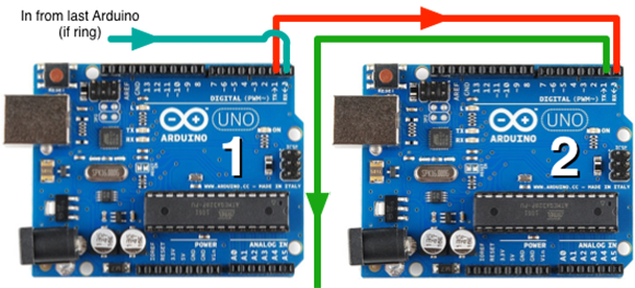
The easiest way to figure this out was to toggle a few of the sensors and look at the data being transmitted. With a good bit of reasoning, [Andrew] figured out how the alarm system’s code worked. This theory was tested by connecting one of the radios up to an Arduino and having his suspicions confirmed.

While [Andrew]’s adventure in reverse engineering is only a benefit for people with this model of security system, it’s a wonderful insight into how to tear things apart and understand them.

Apple MagSafe Protocol Hacking

[Ken Shirriff] was interested in how the Apple MagSafe works. Specifically he wanted to know what controlled the LED on the connector itself so he tore one open to see what is inside. There’s a chip present and he didn’t waste time figuring out how the MagSafe communication protocol works.

The DS2413 chip he found on the MagSafe’s tiny little PCB has just six pins. Two of these control a pair of LEDs, which give the indicator its color range.  Another pin is used for 1-wire communications. When polled the charger will return a 64-bit identification number that includes a variety of information. [Ken] looks into what data is offered from several different models of charger by using the Arduino setup above. But the results are not entirely straight-forward as he discusses in his article. The 1-wire protocol is also used to switch the LEDs. This process is the responsibility of the computer being charged, but [Ken] shows how the colors can be cycled using an Arduino (with a couple of 9-volts as a source instead of a connection to mains).

Communication Protocol For An Indoor Helicopter

propel-execuheli-ir-protocol-revealed

There’s a special type of satisfaction that comes from really understanding how something works at the end of a reverse engineering project. This grid above is the culmination of [Spencer’s] effort to reverse engineer the IR protocol of a Propel ExecuHeli indoor helicopter toy.

The first thing he looked at was the three different controller channels which can be selected to allow multiple helicopters to be used in the same area. [Spencer] was surprised that they all used the same carrier frequency. The secret must be in the coded packets so his next challenge was to figure out how the data was being transmitted via the Infrared signal. It turns out the packets are using pulse-length coding (we were unfamiliar with this protocol but you can read a bit more about it here). The last piece of the puzzle was to capture packets produced by each unique change of the control module. With each bit (except for bit 11) accounted for he can now format his own codes for a controller replacement. Perhaps he’s looking to make the helicopter autonomous?

Inventing Networking Protocols For Dozens Of Arduinos

chain

When you don’t want to use I2C or SPI, and MIDI and DMX are old hat, [Scott] comes along and invents a very strange networking protocol that is just daisy chaining a few Arduinos together with serial connections.

Strange as it may seem, this networking protocol actually makes a whole lot of sense. [Scott] is working on an animatronic birdhouse in the vein of Disney’s Imagineers and needed to network a whole bunch of Arduinos without using up precious IO pins.

The networking stack [Scott] came up with capitalizes on the hardware UART in each Arduino by simply daisy-chaining several boards together. By adding an FTDI breakout at the beginning of the chain, [Scott] can control dozens of Arduinos straight from a terminal

[Scott] isn’t using off-the-shelf Arduinos for this project – a few months ago he found 100 Arduino-compatible stepper motor controllers while dumpster diving at his job, giving him more than enough nodes to come up with some pretty crazy networking protocols. It’s a great use of the hardware he has on hand, and a very clever solution to controlling dozens of microcontrollers at once.

Check out [Scott]’s demo after the break.

Continue reading “Inventing Networking Protocols For Dozens Of Arduinos”

Reverse Engineering A Syma 107 Toy Helicopter IR Protocol

Half the fun of buying toys for your kids is getting your hands on them when they no longer play with them. [Kerry Wong] seems to be in this boat. He bought a Syma S107G helicopter for his son. The flying toy is IR controlled and he reverse engineered the protocol it uses. This isn’t the first time we’ve seen this type of thing with the toy. In fact, we already know the protocol has been sniffed and there is even a jammer project floating around out there. But we took a good look at this because of what you can learn from [Kerry’s] process.

He starts by connecting an IR photo diode to his oscilloscope. This gave him the timing between commands and allowed him to verify that the signals are encoded in a 38 kHz carrier signal. He then switched over to an IR module designed to demodulate this frequency. From there he captures and graphs all of the possible control configuration, establishing a timing and command set for the device. He finishes it off by building a replacement controller based on an Arduino. You can see a video of that hardware after the break.

Continue reading “Reverse Engineering A Syma 107 Toy Helicopter IR Protocol”

Reverse Engineering An AC Signal Protocol

[Arpad] has spent quite a bit of time reverse-engineering a home automation system, and, as he is quick to point out, presents the information learned for informational purposes only. He’s really done his homework (and documented it well), looking into the US patent application, and figuring out how the protocol works.

If you’re wondering how someone is able to send a signal over an AC sine wave, at least one technique is the proprietary [Universal Powerline Bus]. This works by sending precisely times pulses in conjunction with the wave that would exist normally. Given the correct software on the other end, this can then be decoded and used for whatever data transfer is necessary.

Although as engineers and technologists, we certainly don’t condone stealing patents,  part of point of one is that others are allowed to learn your secrets in exchange for some legal protection. [Arpad]’s motivation in doing this is that the technology is only widely available in the US with our puny 120 VAC 60Hz power. With this knowledge, he’s been able to transfer it to work with European 230 VAC 50Hz.

Continue reading “Reverse Engineering An AC Signal Protocol”

Diving Deep Into The Game Boy LCD Protocol

[Craig] wanted to make the original Game Boy LCD screen do his bidding so he sniffed out the data protocol that it uses. We were amused when he mentions that there’s an army of people out there looking to build pointless crap as part of a hobby. Guilty. And he goes on to outline why this LCD screen is a great resource for hobbiests.

As you can see in the pinout above, it uses 5V logic, with a 4 MHz data clock. These traits are both very friendly to a wide range if inexpensive microcontrollers. If you know how to address the display it should be very easy to use. Furthermore, the low pin count is thanks the to a 4-shade grayscale screen, limiting the data pins to just two. [Craig] hooked up his Saleae Logic probe to capture communications and walks us through what he discovered. During this process he proved to himself that he had figured out the protocol by exporting captured data from the logic probe and reassembling it into an image on his computer.