Two months after its surprise reveal at the 2019 East Coast RepRap Festival, the Prusa Mini has started shipping out to the first wave of early adopters. True to form, with the hardware now officially released to the public, the company has begun the process of releasing the design as open source. In their GitHub repository, owners can already find the KiCad files for the new “Buddy” control board and STLs for the machine’s printable parts.
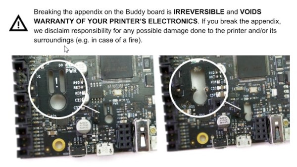
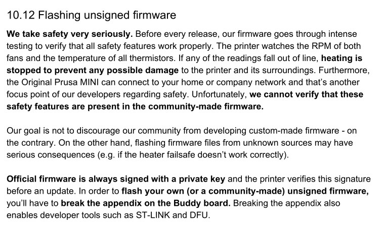
But even so, not everyone feels that Prusa Research has made the Mini as “open” as its predecessors. Some concerned owners have pointed out that according to the documentation for the Buddy board, they’ll need to physically snap off a section of the PCB so they can flash custom firmware images via Device Firmware Upgrade (DFU) mode. Once this piece of the board has been broken off, which the documentation refers to as the Appendix, Prusa Research will no longer honor any warranty claims for the electronic components of the printer.
 For the hardcore tinkerers out there, this news may come as something of a shock. Previous Prusa printers have enjoyed a fairly active firmware development community, and indeed, features that started out as user-developed modifications eventually made their way into the official upstream firmware. What’s more, certain hardware modifications require firmware tweaks to complete.
Prusa Research explains their stance by saying that there’s no way the company can verify the safety of community developed firmware builds. If thermal runaway protections have been disabled or otherwise compromised, the results could be disastrous. We’ve already seen it happen with other printers, so it’s hard to fault them for being cautious here. The company is also quick to point out that the installation of an unofficial firmware has always invalidated the printer’s warranty; physically breaking the board on the Mini is simply meant as a way to ensure the user understands they’re about to leave the beaten path.
How much support is a manufacturer obligated to provide to a user who’s modified their hardware? It’s of course an issue we’ve covered many times before. But here the situation is rather unique, as the user is being told they have to literally break a piece off of their device to unlock certain advanced functionality. If Prusa wanted to prevent users from running alternate firmware entirely they could have done so (or at least tried to), but instead they’ve created a scenario that forces the prospective tinkerer to either back down or fully commit.
So how did Prusa integrate this unusual feature into their brand new 32-bit control board? Perhaps more importantly, how is this going to impact those who want to hack their printers? Let’s find out.
Continue reading “Prusa Dares You To Break Their Latest Printer” →