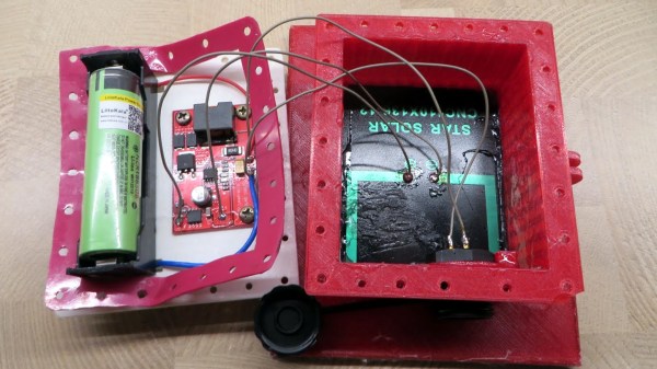
Purge Buckets To Help With Multimaterial Printing

3D printing is cool, but most basic fused deposition printers just print in a single color. This means that if you want a prettier, more vibrant print, you need to paint or perform some other kind of finishing process. Multimaterial printers that can switch filaments on the fly exist, but they often have an issue with waste. [3DMN] decided to attempt building a purge bucket as a solution.

[3DMN] was previously familiar with using a purge block when running multimaterial prints. A basic block model is printed along side the actual desired part. The block is printed so that it is at the same layer height as the desired part, so the nozzle can purge cleanly without stringing plastic all over the print bed.

Tired of the waste, [3DMN] designed a purge bucket which moves with the Z-axis of his Geeetech A20M printer. The bucket attaches to the Z-axis with lock nuts and is always at the same height relative to the nozzle, regardless of the stage of printing. When a material change is required, the nozzle moves to the bucket, purges the filament, and then moves back to the print. The bucket features a 3mm silicone wiper to help ensure there is no material left clinging to the nozzle after the purge is complete, and aluminium tape which helps prevent the purged filament sticking to the walls of the bucket.

[3DMN] notes there’s also a speed increase for some prints, due to no longer needing to print purge objects along with the main part. The parts are available on Thingiverse for those of you wishing to experiment with your own setup.

Multimaterial printing can have some great visual results, and it’s great to see the community providing solutions to improve the process and reduce the waste involved.  We’ve also seen filament splicing, which is another unique approach to multimaterial prints. Video after the break.

Continue reading “Purge Buckets To Help With Multimaterial Printing”

Finite Element Analysis Results In Smart Infill

If you would like to make a 3D print stronger, just add more material. Increase the density of the infill, or add more perimeters. The problem you’ll encounter though is that you don’t need to add more plastic everywhere, only in the weak areas of the part that will be subjected to the most stress. Studying where parts will be the weakest is the domain of finite element analysis, and yes, you can do it in Fusion 360. With the right techniques, you can make a stronger part on your 3D printer, and [Stefan] is here to show you how to do it.

The inspiration for this build comes from [Adrian Bowyer]’s blog, where he talks about adding ‘fibers’ to the interior of 3D printed objects to increase strength. These ‘fibers’ aren’t really fibers at all, but long, thin, cylindrical voids. The theory of this is that the slicer will interpret this as a hole and place perimeters around these voids, effectively increasing the density of the infill in a local area in the print. Combine this with finite element analysis, and you get a part that is stronger where it needs to be, and doesn’t waste plastic.

However, there is an easier way. Fusion 360 and ANSYS Finite Element Simulation are both free-ish tools that allow for some amount of finite element analysis on an imported 3D object. This can be used to find the weakest part of any 3D print, and it can this can be exported as a 3D mesh. Slic3r has a modifier mesh function, and combining this finite element analysis mesh (printed at 100% infill) with the original part (printed at 10% or so infill) results in something that’s strong where it needs to be, doesn’t waste plastic, and is much easier to set up than [Adrian Bowyer]’s ‘fiber’ technique.

After printing a few 3D printed hooks with varying degrees and techniques of infill, [Stefan] found the baseline of 2 perimeters failed in a test hook at about 50kg load. The Smart Infill hook failed at about 100kg. Not bad, and the fancy-pants hook only weighs about 30% more.

You can check out a video of the entire toolchain and testing below. Thanks [Keith] for sending this one in.

Continue reading “Finite Element Analysis Results In Smart Infill”

A 3D Printer To PCB Miller Conversion

Got a 3D printer? With a bit of work, you may also have a PCB miller. That’s the basis of this neat hack by [Gosse Adema], who converted an Anet A8 3D printer into a PCB miller by building a holder for a Dremel rotary tool and adapting the GCode. This approach means that the adaptations to the printer are minimal: the only hardware is a 3D-printed holder for the Dremel that replaces the print head. The result is an impressive PCB milling machine that can do double-sided PCBs and make through holes.

The excellent write-up that [Gosse] did on this hack describes how he converted the printer, and how he took an EagleCAD design and converted it into four GCode files. That’s one for each side of the PCB, one for through holes and one for the final outline of the PCB. These are then fed to the 3D printer and cut in turn with an appropriate milling bit on the Dremel.

We’ve featured a few similar conversions before, such as this vintage conversion of a Makerbot and this cheap engraver conversion, but this one is much more detailed than those, covering the entire process from PCB design to final product.

3D Printing With Tomography In Reverse

The 3D printers we’re most familiar with use the fused deposition process, in which hot plastic is squirted out of a nozzle, to build up parts on a layer by layer basis. We’ve also seen stereolithography printers, such as the Form 2, which use a projector and a special resin to produce parts, again in a layer-by-layer method. However, a team from the University of North Carolina were inspired by CT scanners, and came up with a novel method for producing 3D printed parts.

The process, as outlined in the team’s paper.

The technique is known as Computed Axial Lithography. The team describe the system as working like a CT scan in reverse. The 3D model geometry is created, and then a series of 2D images are created by rotating the part about the vertical axis. These 2D images are then projected into a cylindrical container of photosensitive resin, which rotates during the process. Rather than building the part out of a series of layers in the Z-axis, instead the part is built from a series of axial slices as the cylinder rotates.

The parts produced have the benefit of a smooth surface finish and are remarkably transparent. The team printed a variety of test objects, including a replica of the famous Thinker sculpture, as well as a replica of a human jaw. Particularly interesting is the capability to make prints which enclose existing objects, demonstrated with a screwdriver handle enclosing the existing steel shank.

It’s a technique which could likely be reproduced by resourceful makers, assuming the correct resin isn’t too hard to come by. The resin market is hotting up, with Prusa announcing new products at a recent Makerfaire. We’re excited to see what comes next, particularly as the high cost of resin is reduced by economies of scale. Video after the break.

[via Nature, thanks to Philip for the tip!]

Continue reading “3D Printing With Tomography In Reverse”

3D-Printed Tourbillon Demo Keeps The Time With Style

It may only run for a brief time, and it’s too big for use in an actual wristwatch, but this 3D-printed tourbillon is a great demonstration of the lengths watchmakers will go to to keep mechanical timepieces accurate.

For those not familiar with tourbillons, [Kristina Panos] did a great overview of these mechanical marvels. Briefly, a tourbillon is a movement for a timepiece that aims to eliminate inaccuracy caused by gravity pulling on the mechanism unevenly. By spinning the entire escapement, the tourbillon averages out the effect of gravity and increases the movement’s accuracy. For [EB], the point of a 3D-printed tourbillon is mainly to demonstrate how they work, and to show off some pretty decent mechanical chops. Almost the entire mechanism is printed, with just a bearing being necessary to keep things moving; a pair of shafts can either be metal or fragments of filament. Even the mainspring is printed, which we always find to be a neat trick. And the video below shows it to be satisfyingly clicky.

[EB] has entered this tourbillon in the 3D Printed Gears, Pulleys, and Cams Contest that’s running now through February 19th. You’ve still got plenty of time to get your entries in. We can’t wait to see what everyone comes up with!

Continue reading “3D-Printed Tourbillon Demo Keeps The Time With Style”

Geared Cable Winder Keeps Vive Sync Cable Neatly Wound

Long cables are only neat once – before they’re first unwrapped. Once that little cable tie is taken off, a cable is more likely to end up rats-nested than neatly coiled.

Preventing that is the idea behind this 3D-printed cable reel. The cable that [Kevin Balke] wants to make easier to deal with is a 50 foot (15 meters) long Vive lighthouse sync cable. That seems a bit much to us, but it makes sense to separate the lighthouses as much as possible and mount them up high enough for the VR system to work properly.

[Kevin] put a good deal of effort into making this cable reel, which looks a little like an oversize baitcasting-style fishing reel. The cable spool turns on a crank that also runs a 5:1 reduction geartrain powering a shaft with a deep, shallow-pitch crossback thread. An idler runs in the thread and works back and forth across the spool, laying up the incoming cable neatly. [Kevin] reports that the reciprocating mechanism was the hardest bit to print, as surface finish affected the mechanism’s operation as much as the geometry of the mating parts. The video below shows it working smoothly; we wonder how much this could be scaled up for tidying up larger cables and hoses.

This is another great entry in our 3D Printed Gears, Pulleys, and Cams Contest. The contest runs through February 19th, so there’s still plenty of time to get your entries in. Check out [Kevin]’s entry along with all the others, and see what you can come up with.

Continue reading “Geared Cable Winder Keeps Vive Sync Cable Neatly Wound”

3D Print That Charging Dock For Your 3DS

The Switch is the new hotness and everyone wants Nintendo’s new portable gaming rig nestled in a dock next to their TV, but what about Nintendo’s other portable gaming system? Yes, the New Nintendo 3DS can get a charging dock, and you can 3D print it with swappable plates that make it look like something straight out of the Nintendo store.

[Hobby Hoarder] created this charging dock for the New Nintendo 3DS as a 3D printing project, with the goal of having everything printable without supports, and able to be constructed without any special tools. Printing a box is easy enough, but the real trick is how to charge the 3DS without any special tools. For this, [Hobby Hoarder] turned to the small charging contacts on the side of the console. All you do is apply power and ground to these contacts, and the 3DS charges.

Normally, adding contacts requires pogo pins or hilariously expensive connectors, but [Hobby Hoarder] has an interesting solution: just add some metal contacts constructed from LED leads or paper clips, and mount it on a spring-loaded slider. A regular ‘ol USB cable is scavenged, the wires stripped, and the red and black lines are attached to the spring-loaded slider.

There is a slight issue with the charging voltage in this setup; the 3DS charges at 4.6 Volts, and USB provides 5 Volts. If you want to keep everything within exacting specs, you could add an LDO linear regulator, but there might be issues with heat dissipation. You could use a buck converter, but at 0.4 Volts, you’re probably better off going with the ‘aaay yolo’ theory of engineering.

[Hobby Hoarder] produced a few great videos detailing this build, and one awesome video detailing how to print multicolored faceplates for this charging dock. It’s an excellent project, and a great example of what can be done with 3D printing and simple tools.

Continue reading “3D Print That Charging Dock For Your 3DS”