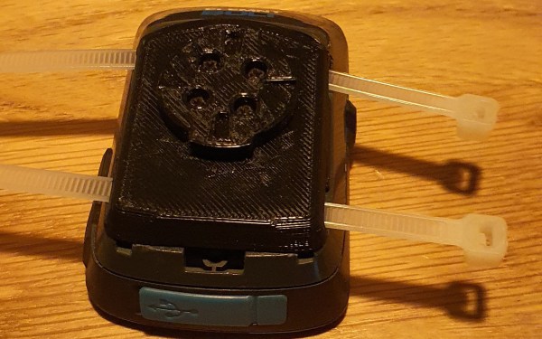
You have a few choices if you want to use a probe to level your 3D printer bed. Rarely, you’ll see optical or capacitive probes. More commonly, though, your probe will sense a metal print or uses a physical probe to touch the print bed. [Design Prototype Test] has long used a BLTouch which uses the latter method. However, putting it in a heated build chamber prevented it from working so he set out to make his own simple design using an Allen key.
We’ve seen Allen key sensors before, but usually, they use a microswitch. We’ve also seen microswitches used to directly probe the bed. But, in this case, a 3D printed fan shroud uses an optical sensor to note when the Allen key hits the bed.
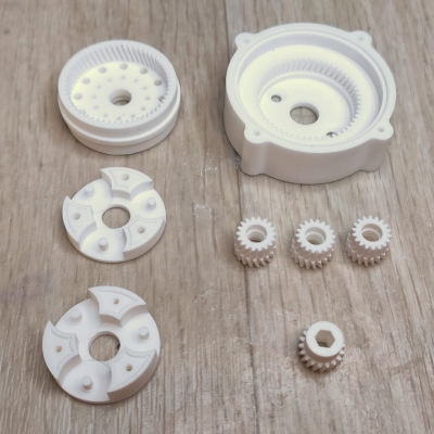
When it comes to making gearboxes, 3D printing has the benefit that it lets you whip up whatever strange gears you might need without a whole lot of hunting around at obscure gear suppliers. This is particularly good for those outside the limited radius served by McMaster Carr. When it came to 3D printed gears though, [Michael Rechtin] wondered whether PLA or resin-printed gears performed better, and decided to investigate.
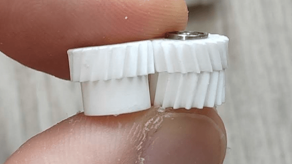
The subject of the test is a 3D-printed compound planetary gearbox, designed for a NEMA-17 motor with an 80:1 reduction. The FDM printer was a Creality CR10S, while the Creality LD02-H was on resin duty.
The assembled gearboxes were tested by using a 100 mm arm to press against a 20 kg load cell so that their performance could be measured accurately. By multiplying the force applied to the load cell by the length of the arm, the torque output from the gearbox can be calculated. A rig was set up with each gearbox pushing on the load cell in turn, with a closed-loop controller ensuring the gearbox is loaded up to the stall torque of the stepper motor before letting the other motor take over.
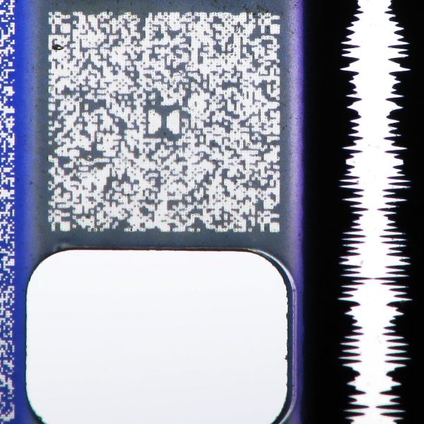
An interesting research project out of MIT shows that it’s possible to embed machine-readable labels into 3D printed objects using nothing more than an FDM printer and filament that is transparent to IR. The method is being called InfraredTags; by embedding something like a QR code or ArUco markers into an object’s structure, that label can be detected by a camera and interactive possibilities open up.
One simple proof of concept is a wireless router with its SSID embedded into the side of the device, and the password embedded into a different code on the bottom to ensure that physical access is required to obtain the password. Mundane objects can have metadata embedded into them, or provide markers for augmented reality functionality, like tracking the object in 3D.
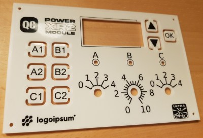
How are the codes actually embedded? The process is straightforward with the right tools. The team used a specialty filament from vendor 3dk.berlin that looks nearly opaque in the visible spectrum, but transmits roughly 45% in IR. The machine-readable label gets embedded within the walls of a printed object either by using a combination of IR PLA and air gaps to represent the geometry of the code, or by making a multi-material print using IR PLA and regular (non-IR transmitting) PLA. Both provide enough contrast for an IR-sensitive camera to detect the label, although the multi-material version works a little better overall. Sadly, the average mobile phone camera by itself isn’t sufficiently IR-sensitive to passively read these embedded tags, so the research used easily available cameras with no IR-blocking filters, like the Raspberry Pi NoIR.
The PDF has deeper details of the implementation for those of you who want to know more, and you can see a demonstration of a few different applications in the video, embedded below. Determining the provenance of 3D printed objects is a topic of some debate in the industry, and it’s not hard to see how technology like this could be used to covertly identify objects without compromising their appearance.
It’s a special gut-dropping, grumbly moment that most who use 3d printers know all too well. When you check on your 13-hour print, only to see that it failed printing several hundred layers ago. [Stephan] from [CNC Kitchen] has a few clever tricks to resume failed prints.
It starts when you discover your print has failed and whether the part is still attached to the bed. If it has detached, the best you can do is whip out your calipers to get a reasonably accurate measurement of how much has been printed. Then slice off the already printed section, print the remainder, and glue the two parts together. If your part is attached to your print bed and you haven’t shifted the plate (if it is removable), start by removing any blemishes on the top layer. That will make it smooth and predictable as it’s starting a new print, just on top of an existing one. Measuring the height that has been printed is tricky since you cannot remove it. Calipers of sufficient length can use their depth function, but you might also be able to do a visual inspection if the geometry is unique enough. After you load up your model in a G-Code viewer, go through it layer by layer until you find what matches what has already been printed.
The last (and perhaps most clever) is to use the printer as a makeshift CMM (coordinate measuring machine). You manually step the printer until it touches the top of the part, then read the z-axis height via a screen or M114 command. A quick edit to the raw G-Code gives you a new file that will resume precisely what it was doing before. If you can’t rehome because the head can’t clear the part, [Stephan] walks you through setting the home on your printer manually.
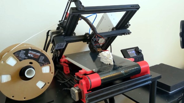
[Call Me Swal] wanted to experiment with large 3D prints. So he took a Hornet 3D printer and designed a lot of 3D parts to convert it into an “infinite” conveyor belt printer. It looks like — as you can see in the video below — that all the parts are 3D printed but you will still need to buy material for the actual belt.
Of course, you may not have a Hornet, but the idea would be applicable to just about any similar printer. You’d have to, of course, adapt or redesign the parts.
Researchers at the University of Texas have been experimenting with optical 3D printing using near infrared (NIR) light instead of the more traditional ultraviolet. They claim to have a proof of concept and, apparently, using NIR has many advantages. The actual paper is paywalled, but there are several good summaries, including one from [3D Printing Industry].
UV light degrades certain materials and easily scatters in some media. However, decreasing the wavelength of light used in 3D printing has its own problems, notably less resolution and slower curing speed. To combat this, the researchers used an NIR-absorbant cyanine dye that exhibits rapid photocuring. The team reports times of 60 seconds per layer and resolution as high as 300 micrometers. Nanoparticles in the resin allow tuning of the part’s appearance and properties.
One custom, compliant heat exchanger, coming right up!
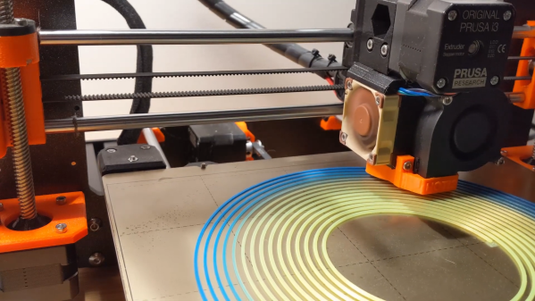
[Thane Hunt] needed to find a way to make a variety of different heat-seal patterns on a fluid heat exchanger made from polyolefin film, and didn’t want all the lead time and expense of a traditional sealing press machined from a steel plate. Pattern prototyping meant that the usual approach would not allow sufficient iteration speed and decided to take a CNC approach. Now, who can think of a common tool, capable of positioning in the X-Y plane, with a drivable Z axis and a controlled heat source? Of course, nowadays the answer is the common-or-garden FDM 3D printer. As luck would have it, [Thane] had an older machine to experiment with, so with a little bit of nozzle sanding, and a sheet of rubber on the bed, it was good to go!
Custom seal path made in Onshape
Now, heat sealing is usually done in a heated press, with a former tool, which holds the material in place and gives a flat, even seal. Obviously this CNC approach isn’t going to achieve perfect results, but for proof-of-concept, it is just fine. A sacrificial nozzle was located (but as [Thane] admits, a length of M6 would do, in a pinch) and sanded flat, and parallel to the bed, to give a 3mm diameter contact patch. A silicone rubber sheet was placed on the bed, and the polyolefin film on top. The silicone helped to hold the bottom sheet in place, and gives some Z-axis compliancy to prevent overloading the motor driver. Ideally, the printer would have been modified further to move this compliancy into the Z axis or the effector end, but that was more work. With some clever 3D modelling, Cura was manipulated to generate the desired g-code (a series of Z axis plunges along a path) and a custom heated indenter was born!