Machine learning is starting to come online in all kinds of arenas lately, and the trend is likely to continue for the forseeable future. What was once only available for operators of supercomputers has found use among anyone with a reasonably powerful desktop computer. The downsizing isn’t stopping there, though, as Microsoft is pushing development of machine learning for embedded systems now.
The Embedded Learning Library (ELL) is a set of tools for allowing Arduinos, Raspberry Pis, and the like to take advantage of machine learning algorithms despite their small size and reduced capability. Microsoft intended this library to be useful for anyone, and has examples available for things like computer vision, audio keyword recognition, and a small handful of other implementations. The library should be expandable to any application where machine learning would be beneficial for a small embedded system, though, so it’s not limited to these example applications.
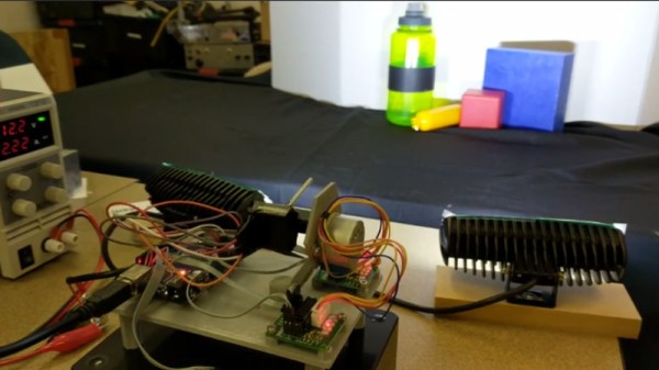
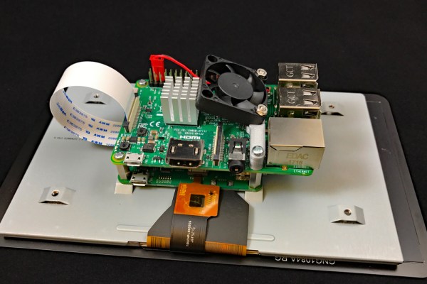
There is one small speed bump to running a machine learning algorithm on your Raspberry Pi, though. The high processor load tends to cause small SoCs to overheat. But adding a heatsink and fan is something we’ve certainly seen before. Don’t let your lack of a supercomputer keep you from exploring machine learning if you see a benefit to it, and if you need more power than just one Raspberry Pi you can always build a cluster to get your task done just a little bit faster, too.
Thanks to [Baldpower] for the tip!