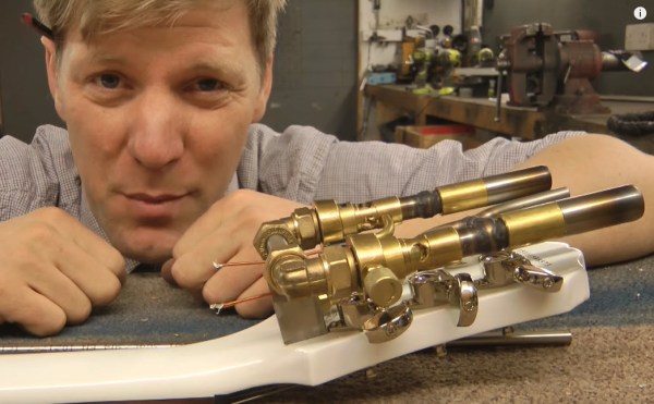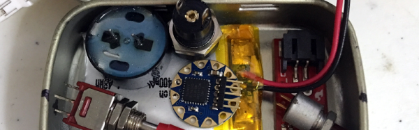
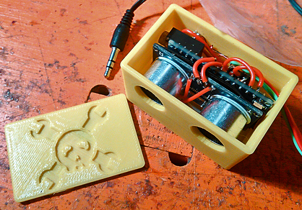
 [Rob Bailey] likes to build things and he likes ham radio. We are guessing he likes mints too since he’s been known to jam things into Altoids tins. He had been thinking about building a code practice oscillator in a Altoids Smalls tin, but wasn’t sure he could squeeze an Arduino Pro Mini in there too. Then he found the TinyLily Mini. The rest is history, as they say, and 1CPO was born.
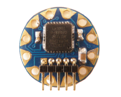
The TinyLily Mini is a circular-shaped Arduino (see right) about the size of a US dime. most of the pads are arranged around the circle and there is a small header that takes a USB programmer. A small rechargeable battery can run the device for a long time.
 [Bokononestly] decided to
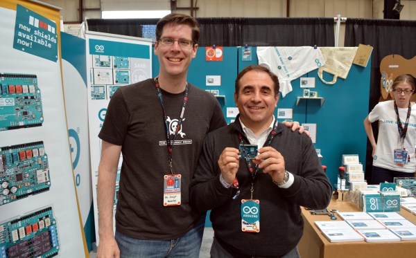
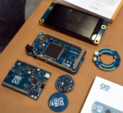 The new boards are called Arduino Primo, Arduino Core, Arduino Alicepad, and Arduino Otto.