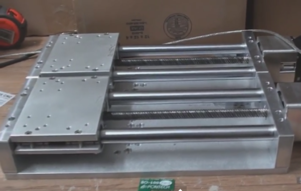
For their Mechanical Engineering senior design project at San Jose State University, [Tyler Kroymann] and [Robert Dee] designed and built a racing motion simulator. Which is slightly out of the budget of most hackers, so before they went full-scale, a more affordable Arduino powered Stewart platform proof of concept was built. Stewart platforms typically use six electric or hydraulic linear actuators to provide motion in six degrees of freedom (6 DOF), surge (X), sway (Y), heave (Z), pitch, roll, and yaw. With a simple software translation matrix, to account for the angular displacement of the servo arm, you can transform the needed linear motions into PWM signals for standard hobby servos.
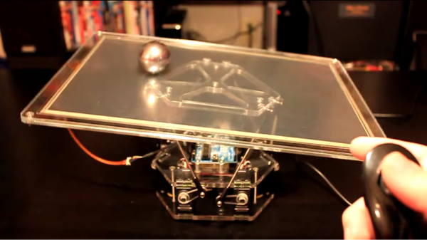
The 6 DOF platform, with the addition of a resistive touch screen, also doubled as a side project for their mechatronic control systems class. However, in this configuration the platform was constrained to just pitch and roll. The Arduino reads the resistive touch screen and registers the ball bearing’s location. Then a PID compares this to the target location generating an error vector. The error vector is used to find an inverse kinematic solution which causes the actuators to move the ball towards the target location. This whole process is repeated 50 times a second. The target location can be a pre-programmed or controlled using the analog stick on a Wii nunchuck.
Watch the ball bearing seek the target location after the break.
Thanks to [Toby] for sending in this tip.
Continue reading “Stewart Platform Ball Bearing Balancer” →