Zappo The Robot Mixes Tone Generator, Sensors, Alarm Clock And More

zappo-clock-bot

Now [Kevin] claims he built this robot for his 3-year-old son but we know he just used that as an excuse to spend way too much time in his workshop. The robot is a roundup of all the interesting things you can do with hobby electronics. It’s a great example of what you can teach yourself in one year, as [Kevin] only started tinkering with electronics about fourteen months ago.

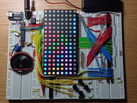
The robot centers around an Arduino which manages to control a plethora of auxiliary boards. The alarm clock part of the build has a readout in the center of the robot’s chest. There are a bunch of sounds which can be played as the alarm, including a lot of iconic movie sound bytes. Add to that some playful features — like a tone generator which is altered by the column of potentiometers on the left, motion activated eyes, and sound activated ears — and you’ve got a dream-come-true of a toy for your kid.

As a side note, we wrote this several days ago, but ended up bumping it a couple of times in the publishing schedule. We reached out to [Kevin] to let him know a feature was on the way. When he learned that we bumped it in order to feature [Jamie Matzel’s] giant robot he had to laugh. The two met at a mini Maker Faire about a year ago and that interaction is what gave [Kevin] the confidence to start the project.

Continue reading “Zappo The Robot Mixes Tone Generator, Sensors, Alarm Clock And More”

A Cable Box Becomes A Network Time Display

DVR

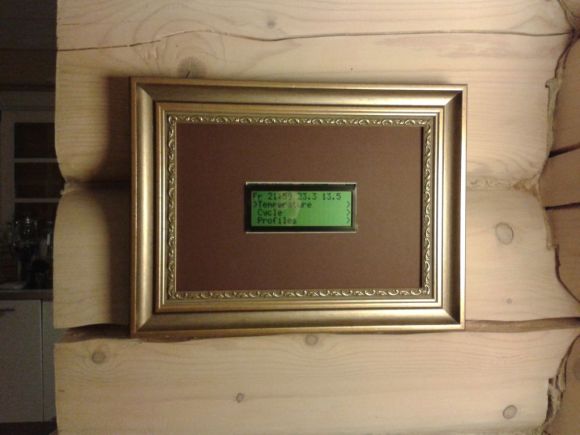
In 2011 [Erkki]’s DVB box gave up the ghost. It had been a fixture of his media center for quite a while, decoding cable and recording shows faithfully for years. A flaky power supply will bring down the mightiest machine, though. and the Topfield box eventually found itself in disuse. One thing [Erkki] liked about this cable box is its wonderful green LED clock – even after the box had been declared dead, he still used it as a clock. Not wanting to keep a faulty machine on life support, [Erkki] decided to strip the guts and replace them with a networked Arduino that receives time over a network

[Erkki] originally used an Arduino and an ENC28J60 Ethernet module to receive time from an NTP server and spit it out onto the LCD display. A full Arduino for this kind of job, especially one that’s a more or less complete project, is a bit overkill so [Erkki] designed a PCB to put his ‘duino to better use.

One interesting bit about this build is that [Erkki] found it completely broken one day. Figuring this was a problem with the microcontroller, he first fried the ATMega with 9 volts – the reasons escape us, however – and started work on programming a new chip. After looking at different ports on his NTP server with a microcontroller, [Erkki] realized he had reset his network switch recently, meaning the previous microcontroller was working perfectly.

In the future, [Erkki] hopes to add some new features to this 8×4 seven-segment display sitting in a large box; something like reading off the temperature, checking IRC and his physical mailbox, and notifying him when someone is at the front door.

A Cold Cathode Audio Visualizer

CC

Finally, cold cathode lights can be used for much more than illuminating the inside of your computer or making your whip look like it can hover. [James] discovered if he varied the voltage going into the inverter, only a certain amount of the tube would light up. Give a hacker an interesting observation and enough time, and eventually he’ll come up with something really cool. In this case, it’s a cold cathode audio visualizer, powered by fluorescent tubes doing unexpected things.

The build details are a little scant, but we were able to coax an imgur album of [James]’ build. He’s using these 20″ CCFL lights with the stock digital inverters replaced with TDK CCFL inverters.

The digital control of this build is provided by an Arduino Mega and a custom shield. We’re guessing the graphic EQ is provided by an MSGEQ7 chip, and the inverters themselves are powered through the Mega’s PWM pins. It’s a lot like an IN-9 Nixie graphic EQ, only much, much bigger. [James] is planning a larger version of this build, dubbed the Mega speKtrum and we can’t wait to see that build along with a proper writeup.

An Introduction To Inertial Navigation Systems

acc_sens

Long before ships relied on GPS to determine their location – and even before radio navigation systems such as LORAN, vessels relied on a still impressively sophisticated means of determining their position: inertial navigation. The theory is simple: if you keep a few very accurate gyroscopes and accelerometers on board, you’ll be able to calculate where you are relative to your previous position. Since electronic gyros and accelerometers are all over the place, [Sebastian] thought he would have a go at creating his own inertial navigation system.

The difficulty in using this method is that every gyroscope invariably has some error. Since the measurements from the gyros and accelerometers are integrated together, the error is also integrated, resulting in an increasing positioning error as time goes on. With a few clever algorithms and very good sensors, it’s possible to minimize this error.

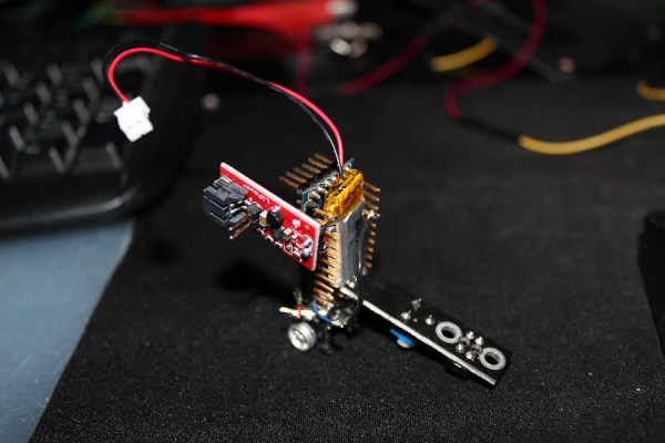
[Sebastian] doesn’t have really great hardware – he’s only working with a accelerometer/gyro breakout board that’s good enough for experimental purposes. After reading the accelerometer data with an Arduino, he’s able to capture all the sensor data and read it into a Python script.

The next steps are to figure out a decent algorithm to integrate all the sensor data, and possibly add a barometer and magnetic compass for better compensation for errors. The project is still in the early phases, but seeing as how an inertial navigation system is one of the engineering triumphs of the early 20th century, we’re eagerly awaiting any progress updates.

2013 Open Hardware Summit Badge Includes EPaper Display

Take a look at this sexy piece for open hardware. It’s what you’ll be wearing around your neck at the Open Hardware Summit this year. WyoLum teamed up with Repaper for the display and Seeed Studios for the boards.

It’s called the BADGEr and it’s both an Arduino and and Arduino shield. There are several different power options; coin-cell, microUSB, unpopulated barrel jack, or the lanyard terminals if you want to wear the power supply around your neck. You can see the five momentary push buttons see above, but on the back you’ll find the microSD card slot along with a power switch for preserving the coin cell.

Check out the video below for a quick look. In addition to acting as your credentials the conference schedule comes preloaded. And of course, this is an Open Source design so you can dig through schematic, board artwork, and code at the page linked above. Oh, and the first hack has already been pulled off. Here’s the badge reading Crime and Punishment.

Speaking of conference badges, DEF CON starts this week. Hackaday writer [Eric Evenchick] will be there and we hope he has a chance to look in on some of the badge hacking at the event.

Continue reading “2013 Open Hardware Summit Badge Includes EPaper Display”

GRBL Compatible Arduino CNC Shield

By the time you get to the point in a home CNC build where you’re adding control electronics you may be ready for the simplest means to an end possible. In that case, grab your Arduino and heat up that etching solution to make your own GRBL compatible shield.

This familiar footprint manages to contain everything you need for a three-axis machine. The purple boards slotted into the pairs of SIL headers are Pololu Stepper motor drivers. Going this route makes replacing a burnt out chip as easy as plugging in a new module. The terminal block in the center feeds the higher voltage rail necessary for driving the motors. The DIL header on the right breaks out all of the connections to the limiting switches (two for each axis), spindle and coolant control, as well as three buttons for pause, resume, and abort. There’s even a header for SPI making it easier to add  custom hardware if necessary.

This is a dual-layer board which may not be ideal for your own fabrication process. [Bert Kruger] posted his Gerber files for download if you want to put in a small run with OSH Park or a similar service.


Turning Kerbal Space Program Into A Proper Space Simulator

Kerbal

Kerbal Space Program – the game of freakin’ space Lego and incompetent little green men – has seen a lot of popularity since it was on the Steam Summer sale. Now, in a bid to out do the flight sim aficionados who build 737 cockpits in their garage, a few enterprising Kerbalnauts are building custom controllers for this wonderful introduction to [Tsiolkovsky], [Goddard], and [Evel Kinevel].

[vladoportos] thought KSP could use custom gaming controllers to provide switches for staging, attitude hold, and reaction control system commands. In the game, these are toggled by keyboard input, but this unfortunately destroys the immersion of being a rocket-powered angel of death for your Kerbal volunteers. He rigged up an Arduino Leonardo to send USB HID commands to his computer whenever he pressed one of the buttons connected to his breadboard controller. It’s a work in progress, but [vladoportos] has some big plans that include a physical nav ball to show his ship’s orientation in space.

USB input is one thing, but that’s only half the problem. If you want to build a real Kerbal ship simulator, you’ll need to get data out of the game, and into your glass or analog displays. [voneiden] over on the KSP subreddit has the solution for you. He’s been working on a ‘mission control’ app that runs in Python, connects to a Kerbal Space Program plugin over TCP, and displays flight information such as speed, altitude, longitude, latitude, apoapsis, and periapsis.  The code is up on his git, ready for some individual to bring this over to a Raspi and a character LCD display.