[Daumemo] likes experimenting with DIY electronics, and like many people, eventually ran across an AVR microcontroller with a Unified Program and Debug Interface (UPDI). One option is of course to purchase an UPDI programmer, but an even better solution was to make a DIY USB version from nice, cheap parts.
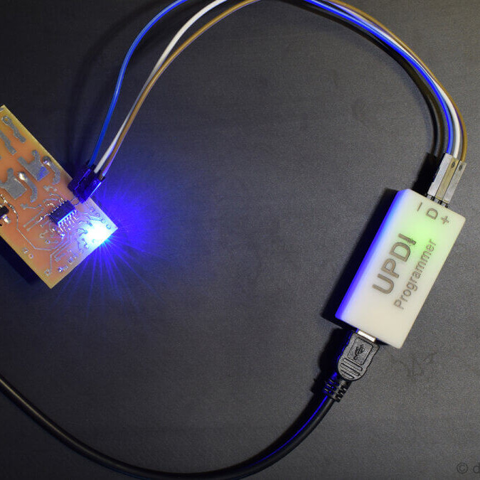
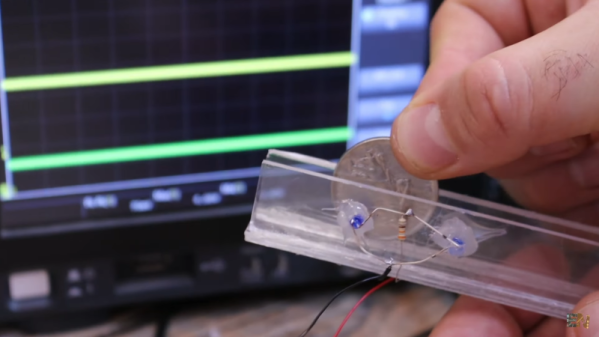
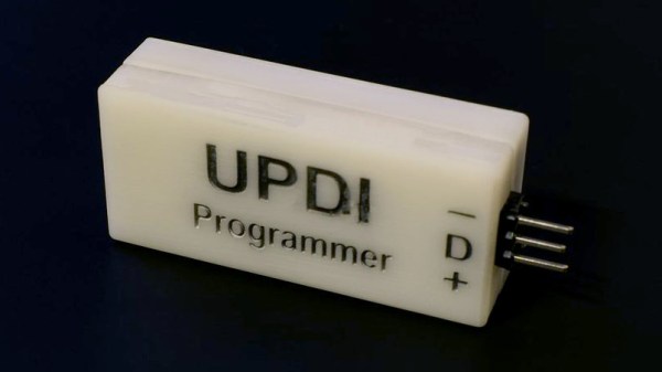
UPDI is an interface for external programming and on-chip debugging of microcontrollers, and [Daumemo]’s solution is based on the jtag2updi project. It combines an Arduino Nano (in this case, a clone) with a single resistor, a single capacitor, and a six pin angled header (with a cleverly bent pin) to enable programming UPDI devices over a USB connection. [Daumemo] is happy to report that the device works just fine in both Microchip Studio with AVRDUDE, or PlatformIO.
Is an Arduino Nano a bit overpowered in this role? Maybe, but the price is certainly right. There’s no need for a custom PCB either, since everything can be soldered direct to the Nano board. A matching 3D printed enclosure is about all that’s needed to make a robust and reliable DIY USB UPDI programmer out of a handful of parts, and that sounds good to us.
On the other hand, if you do find yourself making custom PCBs, you may be interested in another of [Daumemo]’s DIY projects: a printable structure to turn a rotary tool into a PCB drill press.