Remember the Girl Tech IM-me? It was a hot-pink clearance rack toy that suddenly became one of the hottest commodities in the hacking world when it was discovered they could be used for all sorts of radio frequency shenanigans. Now they go for triple digits on eBay, if you can even find one. Well, we’re probably about to see the same thing happen to the Smart Response XE.
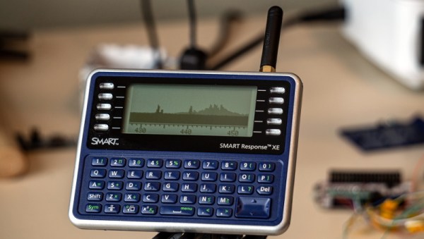
Thanks to the work of a hacker named [ea], this cheap educational gadget is finally starting to live up to the potential we saw in it back when a teardown revealed it was powered by an Arduino-compatible ATmega128RF chip. With a big screen, a decent QWERTY keyboard, and integrated wireless hardware, it seemed obvious that the Smart Response XE was poised to be the next must-have repurposed piece of kit.
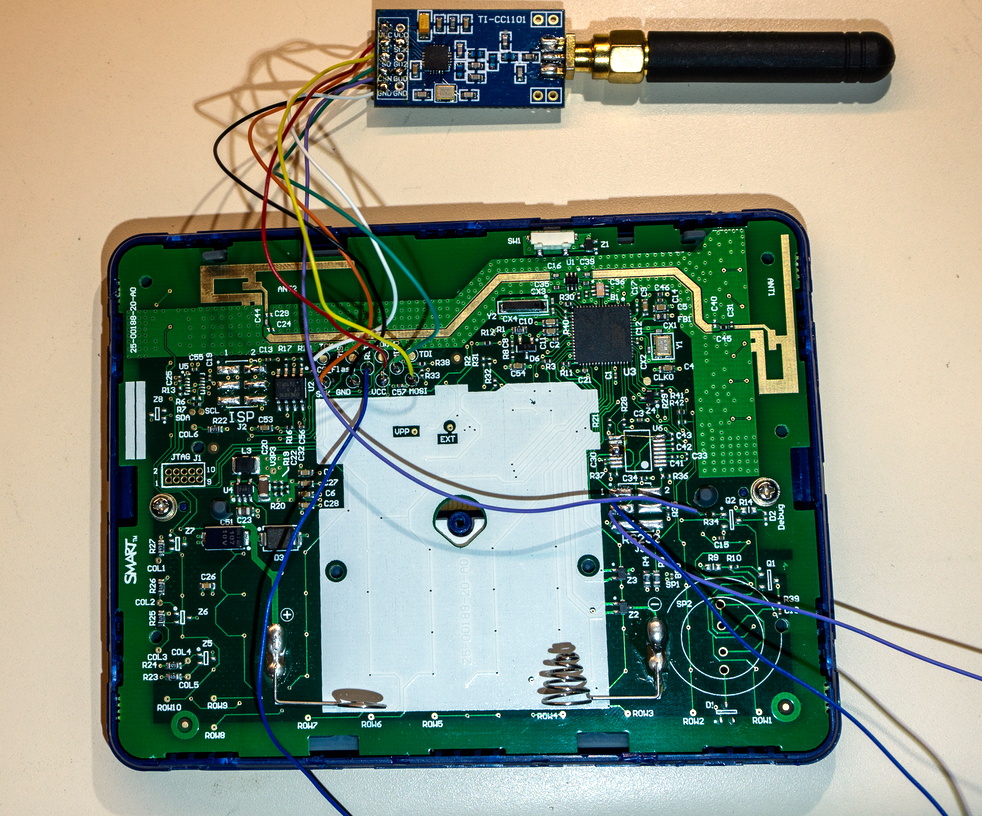 Though as it turns out, [ea] isn’t using the device’s built-in wireless hardware. Step one in this exceptionally well documented and photographed project is to tack a CC1101 transceiver module to the SPI pins on the ATmega128RF. Then with the appropriate firmware loaded up, that nice big screen will show you what’s happening on the 300 MHz, 400 Mhz and 900 MHz bands.
But the fun doesn’t stop there. With the CC1101-modified Smart Response XE, there’s a whole new world of radio hacks you can pull off. As a proof of concept, [ea] has also included a POCSAG pager decoder. Granted the RTL-SDR has already made pulling pager messages out of the air pretty easy, but there’s something to be said for being able to do it on something so small and unassuming.
If you can’t tell, we’re exceptionally interested in seeing what the community can do with the Smart Response XE. At the time of this writing, the going rate on eBay for a good condition unit looks to be about $10 USD, plus the $3 or so for the CC1101 module. But the prices went through the roof when we first posted about it, so get them cheap while you still can.
[Thanks to bburky for the tip.]