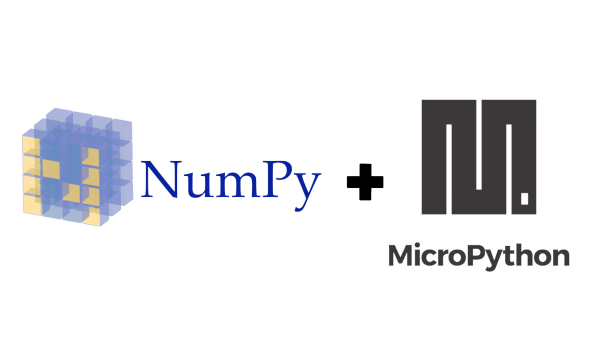
Itty Bitty MIDI Piano Sings With Solenoids

Toy pianos are fun to plink around on for a minute, but their small keyboards and even smaller sound make them musically uninteresting pretty quickly. [Måns Jonasson] found a way to jazz up a two-octave toy piano almost beyond recognition. All it took was thirty solenoids, a few Arduinos, a MIDI shield, and a lot of time and patience.

This particular piano’s keys use lever action to strike thin steel tines. These tines are spaced just wide enough for tiny 5V solenoids to fit over them. Once [Måns] got a single solenoid striking away via MIDI input, he began designing 3D printed holders to affix them to the soundboard.

Everything worked with all thirty solenoids in place, but the wiring was a bird’s nest of spaghetti until he upgraded to motor driver shields. Then he designed a new bracket to hold eight solenoids at once, with a channel for each pair of wires. Every eight solenoids, there’s an Arduino and a motor shield.

The resulting junior player piano sounds like someone playing wind chimes like a xylophone, or a tiny Caribbean steel drum. Check out the build video after the break.

Hate the sound of toy pianos, but dig the convenient form factor? Turn one into a synth.

Continue reading “Itty Bitty MIDI Piano Sings With Solenoids”

Blue Pill Makes Cheap But Powerful Morse Tutor

[W8BH] attended a talk by another ham, [W8TEE] that showed a microcontroller sending and receiving Morse code. He decided to build his own, and documented his results in an 8 part tutorial. He’s using the Blue Pill board and the resulting device sends code with paddles, sends canned text, provides an LCD with a rotary knob menu interface, and even has an SD card for data storage.

All the code is on GitHub. If you are interested in Morse code or in learning how to write a pretty substantial application using the Blue Pill and the Arduino IDE (or any other similar processor), this is a great exposition that is also a practical tool.

Continue reading “Blue Pill Makes Cheap But Powerful Morse Tutor”

Arduino Traffic Light Sings The Song Of Its People

Getting an old traffic light and wiring it up to do its thing inside your house isn’t exactly a new trick; it’s so common that it wouldn’t normally pass muster for these hallowed pages. Even using one up to show the real-time status of your build or system resource utilization would be pushing it at this point. To get our attention, your traffic light is going to need to have a unique hook.

So how did [Ronald Diaz] manage to get his project to stand out from the rest? Interestingly enough, it’s nothing you can see. His traffic light doesn’t just look the part, it also sounds like the real thing. With far more effort and attention to detail than you’d probably expect, he’s made it so his Australian pedestrian traffic light correctly mimics the complex chirping of the original.

Working from a video of the traffic light on YouTube, [Ronald] was able to extract and isolate the tones he was after. Performing spectral analysis on the audio sample, he was able to figure out the frequency and durations of the eleven individual tones which make up the complete pattern. From the 973 Hz tone that only lasts 25 ms to the continuous 500 Hz “woodpecker”, every element of the sound was meticulously recreated in his Arduino code.

The Arduino Pro Mini used to control the traffic light is not only responsible for playing the tones through a piezo speaker, but as you might expect, for firing off the relays which ultimately control the red and green lamps. With everything carefully orchestrated, [Ronald] can now get that authentic Australian side-of-the-road experience without having to leave the comfort of his own home.

If you’d rather your in-home traffic light be more useful than realistic, we’ve got plenty of prior art for you to check out. This traffic light that tells you how the value of Bitcoin is trending is a great example. Or maybe this one that can tell you if the Internet is down.

Continue reading “Arduino Traffic Light Sings The Song Of Its People”

CB Radio + Arduino = 6 Meter Ham Band

Somehow [hvde] wound up with a CB radio that does AM and SSB on the 11 meter band. The problem was that the radio isn’t legal where he lives. So he decided to change the radio over to work on the 6 meter band, instead.

We were a little surprised to hear this at first. Most radio circuits are tuned to pretty close tolerances and going from 27 MHz to 50 MHz seemed like quite a leap. The answer? An Arduino and a few other choice pieces of circuitry.

Continue reading “CB Radio + Arduino = 6 Meter Ham Band”

A SuperCap UPS

If you treat your Pi as a wearable or a tablet, you will already have a battery. If you treat your Pi as a desktop you will already have a plug-in power supply, but how about if you live where mains power is unreliable? Like [jwhart1], you may consider building an uninterruptible power supply into a USB cable. UPSs became a staple of office workers when one-too-many IT headaches were traced back to power outages. The idea is that a battery will keep your computer running while the power gets its legs back. In the case of a commercial UPS, most generate an AC waveform which your computer’s power supply converts it back to DC, but if you can create the right DC voltage right to the board, you skip the inverting and converting steps.

Cheap batteries develop a memory if they’re drained often, but if you have enough space consider supercapacitors which can take that abuse. They have a lower energy density rating than lithium batteries, but that should not be an issue for short power losses. According to [jwhart1], this quick-and-dirty approach will power a full-sized Pi, keyboard, and mouse for over a minute. If power is restored, you get to keep on trucking. If your power doesn’t come back, you have time to save your work and shut down. Spending an afternoon on a power cable could save a weekend’s worth of work, not a bad time-gamble.

We see what a supercap UPS looks like, but what about one built into a lightbulb or a feature-rich programmable UPS?

Dice Reader Brings Tech To Your Craps Game… Or, Ya Know, D&D

There are truisms about dice that you’ve probably already heard: if you have just one of them it’s called a “die”, opposite faces of each die always add up to seven, and those dots that you’re adding together are known as “pips”. But what about the infrared properties of those pips? It turns out they reflect less IR than the white body of the die and that trait can be used to build an automatic die reader.

Great projects have a way of bubbling to the surface. The proof of concept comes from way back in 2009, and while the source blog is now defunct, it’s thankfully been preserved by the Internet Archive. In recreating the project based on that barebones description, [Calvin] reached for a set of five IR transmitter/receiver pairs. Take a close look and you’ll see each transmitter is hidden under its partnered receiver. The light shines up through the receiver and the presence of the pip is detected by measuring how much of it bounces back.

This board is only the sensor portion of the design. A 595 shift register provides the ability to control which IR pair is powered, plus five more signals heading out to the analog pins of an Arduino Uno to monitor how much light is being detected by the receivers. Hey, that’s another interesting fact about dice, you only need to read five different pips to establish the value shown!

We wish there were a demo video showing this in action, but alas we couldn’t find one. We were amused to hear [Calvin] mentioned this was a sorting assignment at University and the team didn’t want to build yet another candy sorter. Look, we love an epic M&M sorter just as much as the next electronic geek, but it’s pretty hard to one-up this dice-based random number generator which rolls 1.3 million times each day.

A Look At The Basics Of Building An Arduino Watch

Miniaturization has made smart watches possible, even for the DIY maker to tinker with. For those just getting to grips with basic digital electronics, it can be daunting, however. For those just starting out, [陳亮] put together a handy guide to building the core of an Arduino-based watch.

The writeup starts at the beginning, going over the basic hardware requirements for a smart watch. This involves considering size, packaging and power draw, as well as the user interface. The build settles on an Arduino Pro Micro, as it uses the ATmega32U4 which eliminates secondary USB-to-serial chips, helping cut down on power consumption. A square IPS LCD display is used to display an analog-style watch face, and time is kept by a DS3231 real-time clock. A pair of small vibration sensors are used to wake the watch when the user moves their wrist to check the time.

While it doesn’t cover the final assembly into a watch-like form factor, it’s a handy guide on what it takes to build a working watch for those who are still getting their feet wet with hardware. Once you’ve got that down, it’s time to contemplate how you’ll build the sleek exterior. Naturally, a good maker has that covered, too.