Get Twelve Charlieplexed PWM Outputs From An ATtiny85

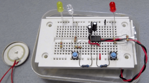
Most of us are aware that charlieplexing can drive a large number of LEDs from a relatively small number of I/O pins, but [David Johnson-Davies] demonstrates adding another dimension to that method to create individually controlled PWM outputs as well. His ATtiny85 has twelve LEDs, each with individually-set brightness levels, and uses only four of the five I/O pins on the device.

Each LED can be assigned a brightness between 0 (fully off) and 63 (fully on). The PWM is done by using one of the timers in the ATtiny85 to generate a periodic interrupt, and the ISR for the interrupt takes care of setting the necessary ratios of on and off times for each charlieplexed output. The result? Twelve flicker-free LEDs with individually addressable brightness levels, using an 8-pin microcontroller and just a few passive components on a tiny breadboard. There’s even one I/O pin left on the ATtiny85, for accepting commands or reading a sensor.

[David] really wrings a lot out of the ATtiny series of microcontrollers with his compact projects, like his Tiny Function Generator (which recently got an update.) He also demonstrated that while charlieplexing is usually used with LEDs, charlieplexing can be used with switches just as easily.

Ultra Tiny PC Plays Snake

[Steve Martin] used to do a comedy act about “Let’s get small!” You have to wonder if [Paul Klinger] is a fan of that routine, as he recently completed a very small 3D printed PC that plays snake. Ok, it isn’t really a PC and it isn’t terribly practical, but it is really well executed and would make a great desk conversation piece. You can see the thing in all its diminutive glory in the video below.

The 3D printer turned out a tiny PC case, a monitor, and a joystick. The PC contains an ATtiny1614, an RGB LED, and some fiber optic to look like case lighting. The monitor is really a little OLED screen. A 5-way switch turns into the joystick.

Continue reading “Ultra Tiny PC Plays Snake”

Be Ready To Roll With Universal Electronic Dice

There are applications you can download for your smartphone that can “roll” an arbitrary number of dice with whatever number of sides you could possibly want. It’s faster and easier than throwing physical dice around, and you don’t have to worry about any of them rolling under the couch. No matter how you look at it, it’s really a task better performed by software than hardware. All that being said, there’s something undeniably appealing about the physical aspect of die rolling when playing a game.

Luckily, [Paul Klinger] thinks he has the solution to the problem. His design combines the flexibility of software number generation with the small form factor of a physical die. The end result is a tiny gadget that can emulate anything from a 2 to 64 sided die with just 6 LEDs while remaining as easy to operate as possible. No need to tap on your smartphone screen with Cheetos-stained hands when you’ve got to make an intelligence check, just squeeze the Universal Electronic Die and off you go. Granted you’ll need to do some binary math in your head, but if you’re the kind of person playing D&D with DIY electronic dice, we think you’ll probably be able to manage.

The 3D printed case that [Paul] came up with for his digital die is very clever, though it did take him awhile to nail it down. As shown in the video after the break, it took seven iterations before he got the various features such as the integrated button “flaps” right. There’s also a printed knob to go on the central potentiometer, to make it easier to select how many sides your virtual die will have.

In terms of the electronics, the design is actually quite simple. All that lives on the custom PCB is a ATtiny1614 microcontroller, the aforementioned LEDs, and a couple of passive components. A CR2032 coin cell powers the whole operation, and it should provide enough juice for plenty of games as it’s only turned on when the user is actively “rolling”.

We’ve seen a number of very impressive electronic dice projects over the years, and it doesn’t look like the trend is slowing down anytime soon. Of course, if you absolutely must hear those physical dice rolling, we can help you with that too.

A Tiny IDE For Your ATtiny

When writing code for the ATtiny family of microcontrollers such as a the ATtiny85 or ATtiny10, people usually use one of two methods: they either add support for the chip in the Arduino IDE, or they crack open their text editor of choice and do everything manually. Plus of course there are the stragglers out there using Eclipse. But [Wayne Holder] thinks there’s a better way.

The project started out as a simple way for [Wayne] to program the ATtiny10 in C under Mac OS, but has since evolved into an open source, cross-platform integrated development environment (IDE) for programming a wide range of ATtiny chips in C, C++, or Assembly. Not only does it integrate the source code editor and programmer, but it even bundles in documentation for common variants of the chips including block diagrams and pinouts; making it a true one-stop-shop for ATtiny hacking.

His IDE runs under Java, including OpenJDK, and [Wayne] provides a stable pre-built executable for those who don’t want to clone the whole GitHub repository. He’s included the GNU/AVR toolchains, though notes that testing so far has been limited to Mac OS, and he’s interested in feedback from Windows and Linux users. Assembly is done either with GNU AVR-AS, or an assembler of his own design, though the latter is currently limited to the ATTiny10.

To actually get the code onto the chip, the IDE supports using the Arduino as a programmer as well as dedicated hardware like the BusPirate or the USBasp. If you go the Arduino route, [Wayne] has even come up with a little adapter board which he’s made available through OSH Park to help wrangle the diminutive chips.

The ATtiny10 might have something of a learning curve, but in exchange this family of tiny microcontrollers offers an incredible amount of capability. When you’re working with what’s essentially a programmable grain of rice, the only limit is your own creativity.

Modernizing A Soviet-era LED Matrix

Used in everything from calculators to military hardware, the 3LS363A is an interesting piece of vintage hardware. With a resolution of 5 x 7 (plus a decimal point), the Soviet-made displays contain no electronics and are simply an array of 36 green LEDs. It’s not hard to drive one of them in a pinch, but [Dmitry Grinberg] thought this classic device deserved a bit better than the minimum.

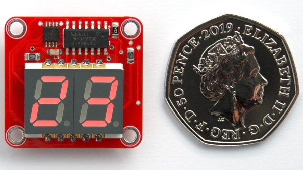
He’s developed a small board that sits behind the 3LS363A and allows you to control it over I2C for a much more modern experience when working with these vintage displays. Powered by the ATtiny406, his adapter board makes it easy to chain the modules together and even handles niceties like flipping the displayed image to account for different mounting positions. While most of us probably won’t have the chance to play around with these relatively rare displays, there’s still plenty of useful information here if you’re thinking of creating your own I2C gadgets.

In his write-up, [Dmitry] explains his rationale behind the design and some of the quirks of working with the display. For example he explains how he gave each column of the display its own FET, but to save space on the board ended up running the single decimal point (technically its own column) directly off of a spare GPIO pin. Relying on the low duty cycle, he even left current limiting resistors off the design. The end result is a tiny board that keeps the same footprint of the 3LS363A itself.

[Dmitry] went all out with developing the firmware for his new “smart” 3LS363A displays, and has written up documentation for the different commands he has implemented. From re-configuring the I2C address to updating the firmware, he’s made sure no stone was left unturned for this project. We’re not ones to shy away from a quick and dirty code, but it’s always nice to see when somebody has really put some thought into the software side of a project.

We’ve seen our fair share of oddball Soviet displays here at Hackaday, utilizing everything from heavy duty incandescent bulbs to remarkably tiny “intelligent” LEDs. While it’s unlikely any of them will dethrone the nixie as king of the retro display devices, it’s always interesting to see unusual hardware being used in the wild.

Ben Heck Can Program The Smallest Microcontroller

Microcontrollers are small, no one is arguing that. On a silicon wafer the size of a grain of rice, you can connect a GPS tracker to the Internet. Put that in a package, and you can put the Internet of Things into something the size of a postage stamp. There’s one microcontroller that’s smaller than all the others. It’s the ATtiny10, and its brethren the ATtiny4, 5, and 9. It comes in an SOT-23-6 package, a size that’s more often seen in packages for single transistors. It’s not very capable, but it is very small. It’s also very weird, with a programming scheme that’s not found in other chips from the Atmel/Microchip motherbrain. Now, finally, we have a great tutorial on using the ATtiny10, and it comes from none other than [Ben Heck].

The key difference between the ATtiny10 and other AVRs is that the tiny10 doesn’t use the standard AVR ISP protocol for programming. Instead of six pins for power, ground, MISO, MOSI, SCK, and RST, this is a high-voltage programming scheme that needs 12 Volts. The normal AVR programmer can do it, but you need to build an adapter. That’s exactly what [Ben] did, using a single-sided perf board, a lot of solder, and some headers. It looks like a lot, but there’s really not much to this programmer board. There’s a transistor and an optocoupler. The only thing that could make this programmer better is an SOT-23 ZIF socket. This would allow bare tiny10s to be programmed without first soldering them to a breakout board, but ZIF sockets are expensive to begin with, and the prices on SOT-23 sockets are absurd.

Programming the device was a matter of loading Atmel Studio and going through the usual AVR rigamarole, but Ben was eventually able to connect a light sensor to the tiny10 and have it output a value over serial. This was all done on a device with only 32 Bytes of RAM. That’s impressive, and one of the cool things about the smallest microcontroller you can buy.

Continue reading “Ben Heck Can Program The Smallest Microcontroller”

Being An SPI Slave Can Be Trickier Than It Appears

Interfacing with the outside world is a fairly common microcontroller task. Outside of certain use cases microcontrollers are arguably primarily useful because of how easily they can interface with other devices. If we just wanted to read and write some data we wouldn’t have gotten that Arduino! But some tasks are more common than others; for instance we’re used to being on the master side of the interface equation, not the slave side. (That’s the job for the TI engineer who designed the temperature sensor, right?) As [Pat] discovered when mocking out a missing SPI GPIO extender, sometimes playing the other role can contain unexpected difficulties.

The simple case for a SPI slave is exactly that: simple. SPI can be wonderful in its apparent simplicity. Unlike I2C there are no weird addressing schemes, read/write bits, stop and start clock conditions. You toggle a clock line and a bit of data comes out, as long as you have the right polarity schemes of course. As a slave device the basic algorithm is of commensurate complexity. Setup an interrupt on the clock pin, wait for your chip select to be asserted, and on each clock edge shift out the next bit of the current word. Check out [Pat]’s eminently readable code to see how simple it can be.

But that last little bit is where the complexity lies. When you’re the master it’s like being the apex predator, the king of the jungle, the head program manager. You dictate the tempo and everyone on the bus dances to the beat of your clock edge. Sure the datasheet for that SRAM says it can’t run faster than 8 MHz but do you really believe it? Not until you try driving that clock a little quicker to see if there’s not a speedier transfer to be had! When you’re the slave you have to have a bit ready every clock edge. Period. Missing even a single bit due to, say, an errant print statement will trash the rest of transaction in ways which are hard to detect and recover from. And your slave code needs to be able to detect those problems in order to reset for the next transaction. Getting stuck waiting to send the 8th bit of a transaction that has ended won’t do.

Check out [Pat]’s very friendly post for a nice refresher on SPI and their discoveries working through the problems of building a SPI slave. There are some helpful tips about how to keep things responsive in a device performing other tasks.